KROHNE TIDALFLUX IFM 4110 PF EN User Manual
Page 15
7.30830.32.00
15
•
Connection diagrams see sect. 2.5.6.
•
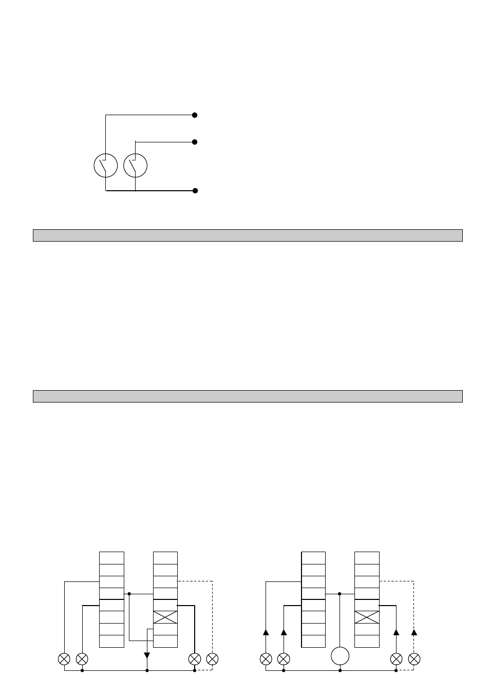
Schematic wiring diagram for status outputs A1/A2 and D1/D2.
These status outputs have MOSFET switches as outputs which switch direct and alternating voltages similar to relay
contacts.
2.5.5
Control inputs C1 and C2
•
Control inputs C1 and C2 are electrically connected (common centre grounding contact C
⊥
) but electrically isolated
from all other circuits.
•
All operating data and functions are adjustable , see Fct. 1.11-1.12.
•
Active mode:
uses the internal power supply, terminals E+/E-
Passive mode:
requires external power supply U
ext
≤
32 V DC / 24 V AC, I
≤
10 mA.
•
The following operating conditions can be initiated using the control inputs:
-
external range change
-
holding of output values
-
zeroing the outputs
-
resetting the internal totalizer
-
resetting (deleting) the error messages
•
Connection diagrams see sect. 2.5.6
2.5.6
Connection diagrams of outputs and inputs
•
Active mode: The IFC 110 PF supplies the power required for operating (driving) the receiver instruments. Observe the
max. operating data (terminals E+/E-).
•
Passive mode: an external power supply source (U
ext
) is required for operating (driving) the receiver instruments.
Groups A / C / D / E / I / P are electrically isolated from each other and from all other input and output circuits.
Please note:
common reference potential
A
⊥
⊥ for A1 and A2
C
⊥
⊥ for C1 and C2
D
⊥
⊥ for D1 and D2
A1 / D1
A
⊥
⊥ / D⊥
⊥
A2 / D2
P
P
D1
D
⊥
D2
C1
C
⊥
C2
I+
I-
A1
A
⊥
A2
E+
E-
Status outputs
D1 / D2 / A1 / A2 active
P
P
D1
D
⊥
D2
C1
C
⊥
C2
I+
I-
A1
A
⊥
A2
E+
E-
_
∼∼
I
I
I
I
U
ext
Status outputs
D1 / D2 / A1 / A2 passive