Yokogawa DR240 User Manual
Page 68
3-23
IM DR232-01E
3
Installation and Wiring
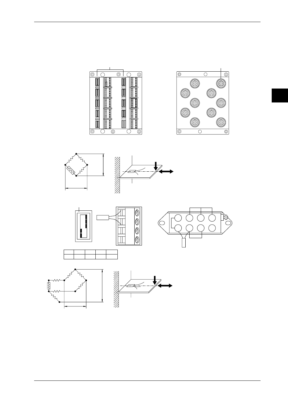
Wiring Strain Input Signal Lines (Strain Input Module)
Please apply the optional DV450-001 strain conversion cable when using a bridge box or strain
gage without sensor line.
Wiring Diagrams
Model with Built-in Bridge
Model with External Bridge Resistors
CH2
CH3
CH5
CH7
CH9
CH1
CH4
CH6
CH8
CH10
Jumper setup switches
CH1
CH3
CH5
CH7
CH9
CH2
CH4
CH6
CH8
CH10
NDI terminal
Wiring Diagrams
• Single-gauge method
ON
OFF
No.1
No.2
No.3
No.4
No.5
A(+)
B(L)
C(-V)
D(H)
DU500-12/DU500-13
Jumper setup switch
DU500-14
E
e
Rg
R
R
R
Rg
No.1
ON
No.2
ON
No.3
ON
No.4
OFF
No.5
OFF
Rg
R = fixed resistor
r = resistance of leadwire
Rg = resistance of strain gauge
e = output voltage developed across bridge
E = voltage imposed across bridge
1
2
3
4
5
6
7
8
• Single-gauge three-wire method
R
R
R
Rg
r
r
r
E
e
R = fixed resistor
r = resistance of leadwire
Rg = resistance of strain gauge
e = output voltage developed across bridge
E = voltage imposed across bridge
3.7 Connecting the Signal Lines