Yokogawa DR240 User Manual
Page 240
13-7
IM DR232-01E
Trouble-shooting
and Maintenance
13
Required Equipment
Name
Measurement
Accuracy
Recommended
Range
DC Voltage Generator
0V to 50V
0.005% of setting+1
µV
Yokogawa 9000*, 4808
DMM
0V to 50V
0.005% of setting+1
µV
HP3458A
Decade Resistance Box
0.1
Ω to 1000Ω
0.01%
Yokogawa 2793
DC Current Generator
0 to 20mA
0.05% of setting
Yokogawa 7651
* For 0V input, it is necessary to either short the input terminals, or to monitor the output voltage using the
DMM.
Calibrating Conditions
Ambient temperature
: 23
°C±2°C
Ambient humidity
: 55
±10%RH
AC power supply voltage : 100 to 240 VAC (AC power supply model)
DC power supply voltage : 12 to 28 VDC (the subunit of DC power supply model omly)
Power supply frequency : 50/60 Hz
±1%
Warm-up time
: at least 30 minutes for this recorder, and necessary warm-up time for
the used equipment
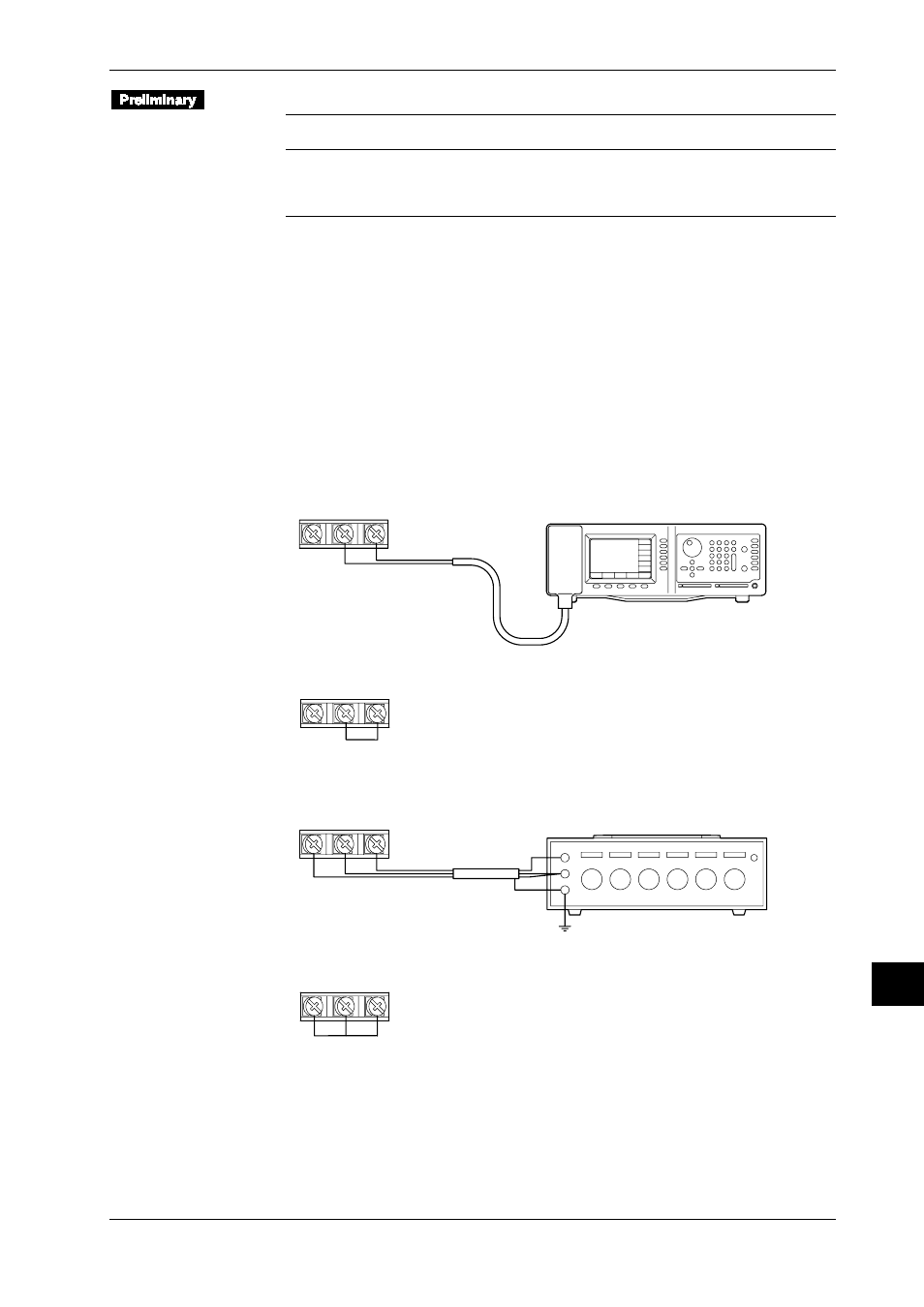
Connection (terminal screw connections)
• DC Voltage Measurement
• Apply a rated voltage in the voltage range that is to be calibrated to channel 3.
+
–
DC Voltage Generator
Input terminal
(CH3)
• Short-circuit between “+” and “–” terminals in channel 2.
+
–
Input terminal
(CH2)
• Temperature Measurement Using RTD
• apply the 100
Ω resistance to channel 5.
B
b
A
Decade Resistance Box
Input terminal
(CH5)
• Short-circuit the resistance input terminals A, B, and b in channel 4.
B
b
A
Input terminal
(CH4)
13.5 Calibration