Yokogawa DR240 User Manual
Page 245
13-12
IM DR232-01E
DISPLAY mode (to display and adjust the calibrated value)
Use this mode only for checking the calibrated value. In this mode, you can adjust the calibrated
value, but, if it is invalid, the instrument may be inoperative. For details, contact your nearest
Sales representative.
• Calibrated-value display items
• Calibrated-value display items vary depending on the type of module to be calibrated.
• For use with universal input modules, display calibrated-value display items in the following
order:
20 mV ZERO
→ 20 mV SPAN → 60 mV ZERO → 60 mV SPAN → 200 mV ZERO →
200 mV SPAN
→ 2 V ZERO → 2 V SPAN → 6 V ZERO → 6 V SPAN → 20 V ZERO →
20 V SPAN
→ 50 V ZERO → 50 V SPAN → Pt: 1 mA ZERO → Pt: 1 mA SPAN → Pt: 2
mA ZERO
→ Pt: 2 mA SPAN → Pt: 1 mA-H SPAN → Pt: 2 mA-H SPAN → Cu: 2 mA
ZERO
→ Cu: 2 mA SPAN
For a mA-input module, show the calibrated values in the order, 20 mA ZERO and 20 mA
SPAN. For a strain input module, show the calibrated values in the following order:
2k ZERO, 2k SPAN, 20k ZERO, 20k SPAN, 200k ZERO and 200k SPAN.
For a digital input module, show the calibrated value in the following order;
60mV ZERO, 60mV SPAN, 6V ZERO, 6V SPAN.
• When the DC V/TC/DI input module is selected, the displayed values for RTD in the
universal input module can be modified without influencing operation of the recorder.
• The calibrated values appear in the above order each time the ENTER key is pressed. If the
MODE key is pressed while displaying calibrated values, the display returns to “A/D
calibration mode selection,” and the calibrated value already adjusted before pressing the
MODE key is canceled. Calibrated values are effective immediately after terminating the
DISPLAY mode.
• Adjustable range and error display
• Adjustable ranges are -32768 to 32767 (excepting 16384, -16384, 16385 and -16383).
• If the following numeric values are set, errors appear.
Outside the range from -32768 to 32767: ERROR002
16384 or -16384: ERROR145
16385 or -16383: ERROR144
Note
• In the adjustable ranges, if the following are not satisfied, the adjusted module is recognized as an error
module.
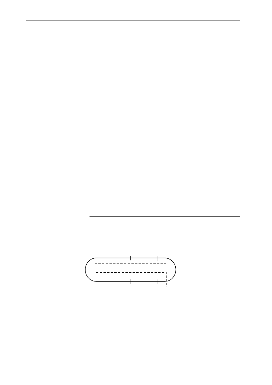
• Calibrated value (ZERO) : -3277 to 3277 (ideal value = 0)
• Calibrated value (SPAN) : 29491 to -29491 (ideal value = -32768)
–29491(21000)
29491(19000)
–32768(20000)
ZERO calibration
SPAN calibration
–3277
0
3277
19000 to 21000 for strain input modules (ideal value: 20000)
Values in ( ) are for strain input modules.
• When calibrating the DC, TC, or DI input module, you need not calibrate an RTD.
END mode (storing a calibrated value in the internal nonvolatile memory)
Select one of the following two:
• STORE : Stores data in the internal nonvolatile memory.
• ABORT : Cancels the storage of data in the internal nonvolatile memory.
13.5 Calibration