Yokogawa DR240 User Manual
Page 256
14-11
IM DR232-01E
Specifications
14
14.2 Universal Input Module and DCV/TC/DI Input
Module
Style Number: S2
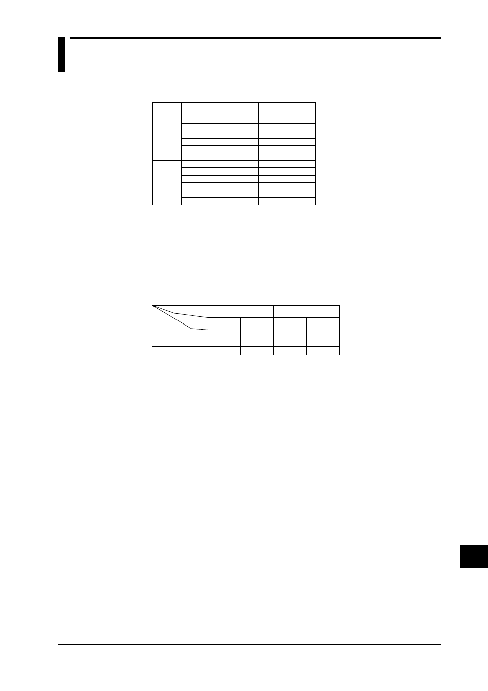
Type, Number of Channels, Terminal Type and Minimum Measurement Interval
0.5s
0.5s
2s
2s
2s
2s
0.5s
0.5s
2s
2s
2s
2s
screw
clamp
screw
clamp
screw
clamp
screw
clamp
screw
clamp
screw
clamp
10ch
10ch
20ch
20ch
30ch
30ch
10ch
10ch
20ch
20ch
30ch
30ch
DU100-11
DU100-12
DU100-21
DU100-22
DU100-31
DU100-32
DU200-11
DU200-12
DU200-21
DU200-22
DU200-31
DU200-32
Kind
Universal
input
module
mV/TC
input
module
Type
Number of
channels
Terminal
type
Minimum measurement
interval
Input method
floating unbalanced input, each channel mutually isolated (channel independent)
The RTD range (DU100 only) has a common potential (terminal b)
A/D resolution
±20000
A/D integration time
20ms (50Hz), 16.7ms (60Hz), 100ms (10Hz) or auto
(Except, auto switch does not function on the subunit (DS400/DS600) of a DC power supply
model. Selecting “AUTO” will set the A/D integration time to 20 ms (50 Hz).)
Minimum measurement interval
number
of channels
20ms/16.7ms
(50Hz/60Hz)
4s
5s
6s
3s
4s
4s
12s
15s
20s
10
20
30
Low-pass filter OFF
Low-pass filter ON
Filter ON/OFF
A/D
integration
time
0.5s*
2s
2s
100ms
(10Hz)
20ms/16.7ms
(50Hz/60Hz)
100ms
(10Hz)
*2s if the power monitor module is installed.
Normal operating temperature/humidity
20 to 80%RH for –10 to 40
°C, 10 to 50%RH for 40 to 50°C, 5 to 30%RH for 50 to 60°C (no condensation)
Compensation for the reference junction
Switchable internally or externally for each channel.
Compensation accuracy for the reference junction
(measured at 0
°C, where the input terminals are balanced)
Type R, S, B, W
:
±1°C
Type K, J, E, T, N, L, U :
±0.5°C
Maximum allowable input voltage
2V DC or lower range, TC, RTD, DI (CONT) :
±10V DC
6V DC or greater range, DI (LEVEL)
:
±60V DC
Normal mode voltage
voltage, TC : 1.2 times the rated range or less (at peak value, including 50 or 60Hz signal
component)
RTD
: 50 mV or lower (at peak value)
Normal mode rejection ratio
40dB or greater (50/60Hz
±0.1%)
Common mode noise voltage
250VAC rms (50/60Hz)
Common mode rejection ratio
120dB or greater (50/60Hz
±0.1%, 500Ω unbalanced, between the negative measurement terminal
and ground)
Maximum noise between channels
150VAC rms (50/60Hz)