Yokogawa DR240 User Manual
Page 67
3-22
IM DR232-01E
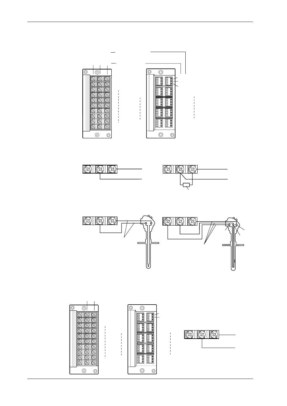
Wiring Input Signal Lines (Universal, DCV/TC/DI, and Digital input modules)
Terminals
Screw type terminal
Clamp type terminal*
2
+
-
A
B
b
DC voltage • TC •
contact
RTD*
1
A
B
b
CH1
CH2
CH10
CH1
CH2
CH3
CH4
CH9
CH10
+
-
*1 There are no RTD
input terminals on
the DCV/TC/DI and
Digital input module.
*2 There is no clamp
type terminal for
Digital input module.
Wiring Diagram
DC voltage input
Compensation lead
DC current input
Shunt resistor
Note:For 4 to 20mA input, shunt
resistance value should
be 250
Ω
±
0.1%
10
Ω
* max./leadwire
Three wire resistances
should be approx. equal.
*10
Ω
max. for Pt100
Ω
and
Pt50
Ω
, 1
Ω
max. for Cu10
Ω
.
DC input
RTD input
TC input
DC voltage input/DI input (contact)
b
A
B
A
b
B
+
-
+
-
+
-
+
-
+
-
Wiring DC-current Input Signal Lines (mA-input Module)
Diagrams of Terminal Block and Wiring
Model with Screw Terminals
Model with Clamp Terminals
+
–
+
–
CH1
CH2
CH10
CH1
CH2
CH3
CH4
CH9
CH10
DC-current input
+
–
+
–
3.7 Connecting the Signal Lines