Yokogawa DR240 User Manual
Page 102
4-12
IM DR232-01E
4.7 Using the RELAY STATUS Display
Relation between the Relay Status and Internal Switch
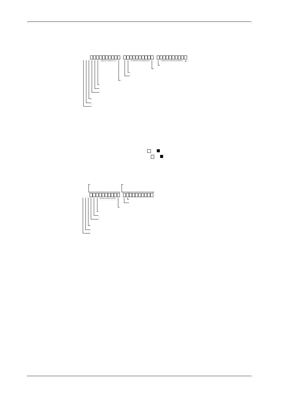
If the relay status of the internal switches is being displayed, an “S” will be displayed as the first
character. The next two characters show the number of the internal switch which corresponds to
the first batch of the display and range from 01 to 51. There are 60 internal switches.
S01
Relay status of internal switch 3
Relay status of internal switch 2
Relay status of internal switch 1
Internal switch 12
Internal switch 11
Internal switch 30
Internal switch 21
Internal switch 20
Internal switch 10
Internal switch no. in units of 1 (fixed to 1)
Tens of internal switch no. (0 to 5)
Internal switch (S)
Relation between the Relay Status and Alarm Output Relay
If the relay status of the alarm output relays is being displayed, a unit number will be displayed in
the first character position. The slot number in the second character position represents the
number of slot in which the alarm module or the DI/DO module is mounted. The alarm output
relay is different in relay status display whether it is in the alarm module or in the DI/DO module
as shown below.
• If an alarm module is mounted, ten or indicators are displayed.
• If the DI/DO module is mounted, ten or indicators are displayed but the right 8 indicators
of ten are not used because two alarm output relays are used.
Example for mounting the alarm module and the DI/DO module:
011
Relay status of alarm output relay 13
Relay status of alarm output relay 12
Relay status of alarm output relay 11
Alarm relay 22
Alarm relay 21
Alarm relay 20
Alarm relay No. (in units of 1)
Slot No.
Unit No.
Display for alarm
module
Display for DI/DO
module
Not used