Yokogawa DR240 User Manual
Page 263
14-18
IM DR232-01E
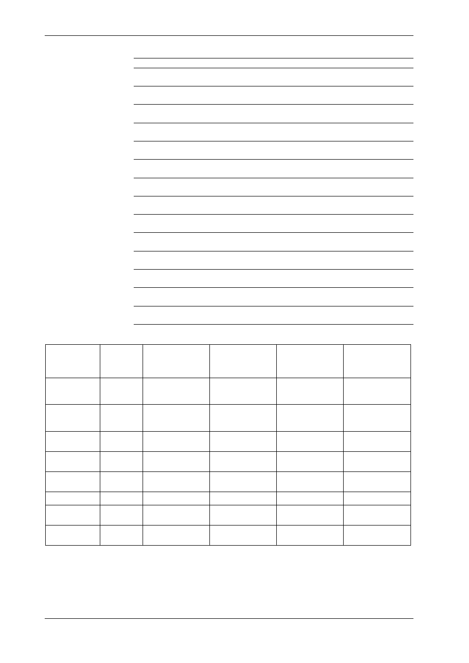
Ranges of Indication
Measured Data Item
25 V-0.5A
25 V-5 A
250 V-0.5 A
250 V-5 A
Effective voltage
0.00 to 26.25 V rms 0.00 to 26.25 V rms 0.0 to 262.5 V rms
0.0 to 262.5 V rms
Vi (i = 1, 2, 3, 13, 0)
Effective current
0.0000 to 0.5250 V rms 0.000 to 5.250 V rms
0.0000 to 0.5250 V rms 0.000 to 5.250 V rms
Ii (i = 1, 2, 3, 13, 0)
Active power
–13.75 to 13.75 W –137.5 to 137.5 W –137.5 to 137.5 W –1375 to 1375 W
P1, P2, P3
Active power
–27.50 to 27.50 W –275.0 to 275.0 W –275.0 to 275.0 W –2750 to 2750 W
P13
Active power
–41.25 to 41.25 W –412.5 to 412.5 W –412.5 to 412.5 W –4125 to 4125 W
P0
Apparent power
0.00 to 13.75 VA
0.0 to 137.5 VA
0.0 to 137.5 VA
0 to 1375 VA
VA1, VA2, VA3
Apparent power
0.00 to 27.50 VA
0.0 to 275.0 VA
0.0 to 275.0 VA
0 to 2750 VA
VA13
Apparent power
0.00 to 41.25 VA
0.0 to 412.5 VA
0.0 to 412.5 VA
0 to 4125 VA
VA0
Reactive power
0.00 to 13.75 Var
0.0 to 137.5 Var
0.0 to 137.5 Var
0 to 1375 Var
Var1, Var2, Var3
Reactive power
0.00 to 27.50 Var
0.0 to 275.0 Var
0.0 to 275.0 Var
0 to 2750 Var
Var13
Reactive power
0.00 to 41.25 Var
0.0 to 412.5 Var
0.0 to 412.5 Var
0 to 4125 Var
Var0
Power factor
–1.00 to 1.00
–1.00 to 1.00
–1.00 to 1.00
–1.00 to 1.00
PFi (i = 1, 2, 3, 13, 0)
Phase
–89.0 to 89.0 deg
–89.0 to 89.0 deg
–89.0 to 89.0 deg
–89.0 to 89.0 deg
PHi (i = 1, 2, 3, 13, 0)
Frequency
41.00 to 69.00 Hz
41.00 to 69.00 Hz
41.00 to 69.00 Hz
41.00 to 69.00 Hz
FREQ
Output Data Items of Each Wiring Method
Output Data Item
Single-phase
Single-phase
Three-phase
Three-phase
Three-phase
Two-wire
Three-wire
Three-wire
Three-wire
Four-wire
(Dual-voltage, (Triple-voltage,
Dual-current)
Triple-current)
Effective voltage V
V1
V1, V3
V1, V3
V1, V2, V3
V1, V2, V3
V13: (V1+V3)/2
V13: (V1+V3)/2
V13: (V1+V3)/2
V0: (V1+V2+V3)/3
V0: (V1+V2+V3)/3
Effective current I
I1
I1, I3
I1, I3
I1, I2, I3
I1, I2, I3
I13: (I1+I3)/2
I13: (I1+I3)/2
I13: (I1+I3)/2
I0: (I1+I2+I3)/3
I0: (I1+I2+I3)/3
Active power W
P1
P1, P3
P1, P3
P1, P2, P3
P1, P2, P3
P13: P1+P3
P13: P1+P3
P13: P1+P3
P0: P1+I2+P3
Apparent power VA VA1
VA1, VA3
VA1, VA3
VA1, VA2, VA3
VA1, VA2, VA3
VA13: VA1+VA3
VA13: VA1+VA3
VA13: VA1+VA3
VA0: VA1+VA2+VA3
Reactive power Var Var1
Var1, Var3
Var1, Var3
Var1, Var2, Var3
Var1, Var2, Var3
Var13: Var1+Var3
Var13: Var1+Var3
Var13: Var1+VA3
Var0: Var1+Var2+Var3
Frequency FREQ
FREQ
FREQ
FREQ
FREQ
FREQ
Power factor PF
PF1
PF1, PF3
PF1, PF3
PF1, PF2, PF3
PF1, PF2, PF3
PF13
PF13
PF13
PF0
Phase angle PH
PH1
PH1, PH3
PH1, PH3
PH1, PH2, PH3
PH1, PH2, PH3
PH13
PH13
PH13
PH0
14.4 Specifications of Power Monitor Module