Yokogawa DR240 User Manual
Page 241
13-8
IM DR232-01E
• DC Current Measurement
Apply the 20mA to channel 3
+
–
Input terminal
(CH3)
DC Current Generator
Short circuit between “+” and “–” terminal in channel 2
+
–
Input terminal
(CH2)
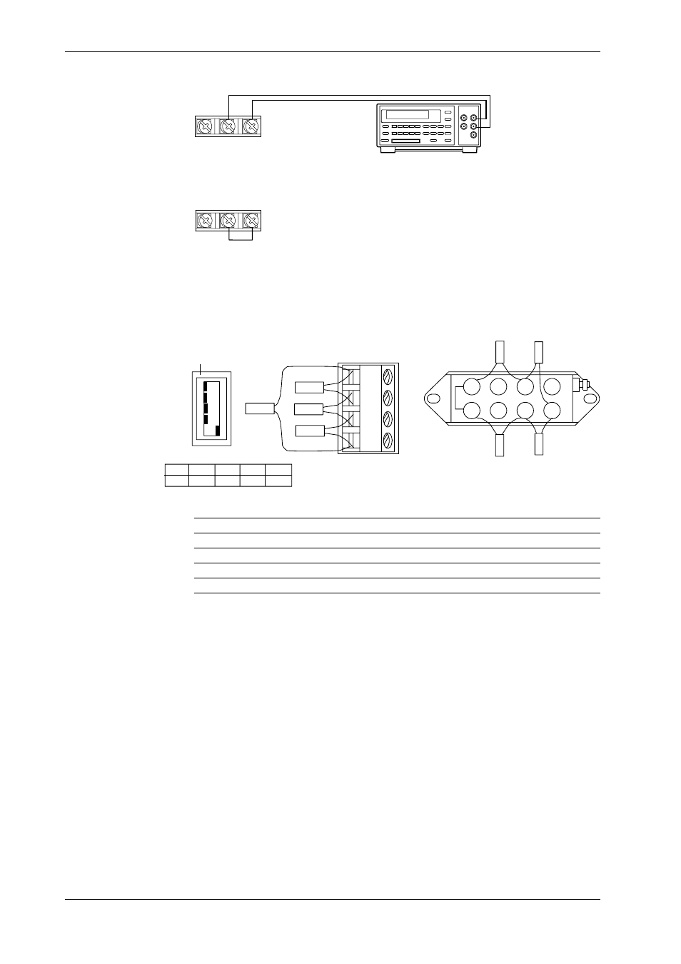
• Strain measurement
Perform calibrations using 4-gauge method.
Use a 319300 bridge box for the Du500-14’s bridge box.
Wire the strain gauge or the bridge box to the channel 2.
Jumper setting switch
ON
OFF
No.1
No.2
No.3
No.4
No.5
A(+)
B(L)
C(-V)
D(H)
DU500-12/DU500-13
DU500-14
No.1
OFF
No.2
OFF
No.3
OFF
No.4
OFF
No.5
ON
1
2
3
4
5
6
7
8
R4
R2
R3
R1
R2
R4
R3
R1
To R1 to R4, connect resistors with the specifications described below.
Calibration
Resistors R1, R2&R3
Resistor R4
Accuracy
ZERO
120.000
120.000
±0.005%, ±0.3ppm/°C
2k SPAN
120.000
119.521
±0.005%, ±0.3ppm/°C
20k SPAN
120.000
115.294
±0.005%, ±0.3ppm/°C
200k SPAN
120.000
80.000
±0.005%, ±0.3ppm/°C
13.5 Calibration