3 how to connect the input/output modules, How to connect the input/output modules -7, Warning – Yokogawa DR240 User Manual
Page 52: Setting the unit number of each subunit, Connecting method, Modules which can be used
3-7
IM DR232-01E
3
Installation and Wiring
3.3
How to Connect the Input/Output Modules
WARNING
When connecting the Input/Output modules, make sure to turn OFF the
power to the DR232/DR242/DS400/DS600 to prevent an electric shock
or damage to the instrument.
Setting the Unit Number of each Subunit
When connecting subunits to the DR232/DR242, it is necessary to assign a distinctive unit-
number to each subunit. This number can be selected from 0 to 5 (the setting 6 and up will not be
recognized) and is set, as shown in the figure below, by a setting switch (rotary dipswitch).
Note
When you connect an input module at the location of the setting switch, the switch can not be operated
anymore. Therefore, make sure you set the switch before connecting any input module there.
It is convenient for confirming unit numbers to write each unit number setting on the gray concave surface
at the top of DS600 subunit (or on the left side of DS400 subunit).
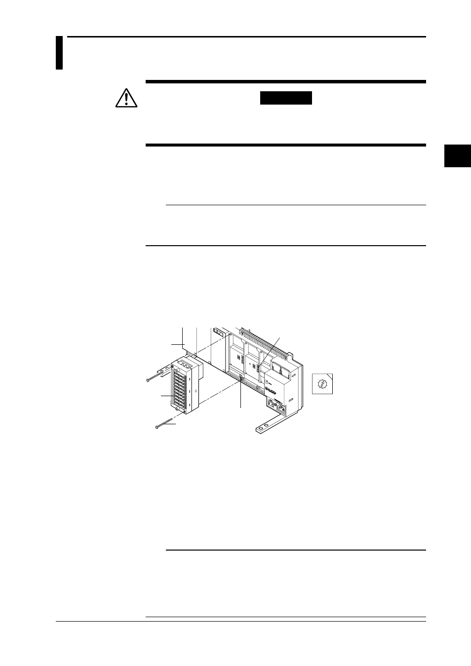
Connecting Method
1. Verify that the power to the DR232/DR242/DS400/DS600 has been turned OFF.
2. Remove the cover of the location where the module will be connected. Do not remove any
cover of locations where no module will be connected.
3. Hold the input unit so that the male part of the connector at the back side of the input unit
matches the female part of the receiving connector. Then connect the unit.
4. Fasten the input unit by fastening the two accessory M3 screws.
0 1
2
3
45
6
7
8
9
Module connector
Screws to fasten the module
Input
module
Switch for setting
the unit number
• Switch for setting the
unit number
(settable from 0 to 5)
Cover
Modules Which Can be Used
Not more than one DI/DO module can be connected to all units.
• Main unit DR232/DR242
Alarm module, DI/DO module, and communication interface module.
(Note: The input module cannot be connected.)
Number of modules that can be connected: 1
• Subunit DS400/DS600
Input module, alarm module, and DI/DO module.
Number of modules that Dqn be connected: 4 for DS400, 6 for DS600 (up to 300)
DS400: Input module + alarm module + DI/DO module: max. four
DS600: Input module + alarm module + DI/DO module: max. six
Note
• No alarm module or DI/DO module can be connected to the right side of an input module, since the rise
in temperature would hinder the measurement accuracy. Verify the type of module by the seal on the top
side.
• Do not connect the universal input module and the power monitor module in slots next to eachother.
Keep them at least 1 slot apart. If you mount the power module immediately beside the universal
module, the measuring accuracy of the universal module may fall out of its guaranteed range because of
the heat radiating from the power module.