Connecting rs-485 communications – Watlow MLS User Manual
Page 55
Installation
MLS User’s Guide 43
1. Plug the phone connector into the slot labeled "RS-232/RS-485" on
the rear of the MLS-PM.
2. Plug the D-sub connector into the communications connector.
This table shows RS-232 connections for 25-pin and 9-pin connectors.
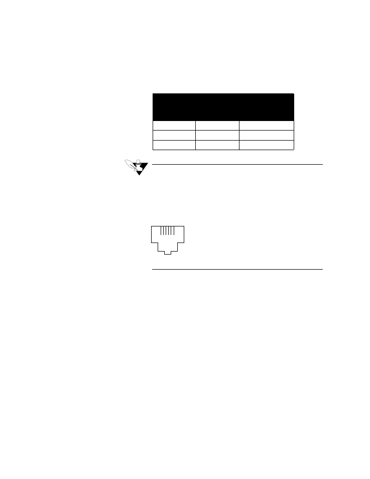
NOTE
The pin numbers and colors are not industry stan-
dard. Watlow-Anafaze numbers the pins from
right to left with 1 on the right as you’re looking at
the back of the MLS-PM. Colors vary depending
on the manufacturer. The figure below shows a
back of an MLS-PM.
Connecting RS-485 Communications
RS-485 specification is for "balanced line" operation; it is not true
differential, so you must supply a common ground connection. Use a
fifth wire (which should not be shield, if possible) or a common ground
connection to establish the common ground.
Do not use the common ground connection unless the common mode
voltage between stations at your installation exceeds the RS-485
specification of 7 volts peak; in that case, use a fifth wire.
The following diagram shows the recommended system hookup. The
transmitter from the host computer connects in parallel to the controller
receivers, and the host computer receiver connects in parallel to the
controller transmitters. Watlow-Anafaze recommends that you use a
single "daisy chain" rather than "octopus connections" or "spurs". In
addition, use a terminating resistor (a 200 ohm resistor laid across the
line at the furthest point from the transmitter) at each end of the
transmission line.
This figure shows the MLS RS-485 connections.
Computer Connector
MLS RS-232 Pin
Number
DB 25
DB 9
RX Pin 3
RX Pin 2
TX Pin 5 Yellow
TX Pin 2
TX Pin 3
RX Pin 1 Blue
GND Pin 7
GND Pin 5
GND Pin 4 Green
1
6