Watlow MLS User Manual
Page 129
Troubleshooting
MLS User’s Guide 117
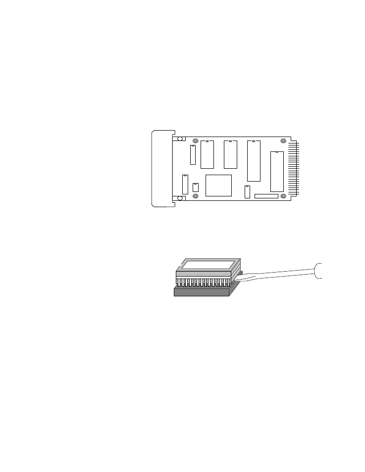
5. Locate the EPROM on the circuit board. The EPROM is a 28-pin
socketed chip which may have an ANAFAZE label on top of it. If
there is no label, a small window will be visible in the middle of the
top of the chip.
Do not confuse the EPROM with the RAM; the RAM also has 28
pins, but it is in a high-profile socket, and it does not have a label or a
window. (The component designation U2 is printed on the processor
board next to the EPROM socket.)
The next figure shows the EPROM and the RAM chip..
6. Remove the existing EPROM from its socket by prying it out with a
small flathead screwdriver, as shown below.
7. Carefully bend the legs of the new EPROM against a flat surface until
they line up with the holes in the EPROM socket.
8. Carefully insert the new EPROM into the EPROM socket. Make sure
that the chip is oriented so that its notch faces the same way as the
part outline on the board.
9. Reverse steps 2 through 4 to reassemble the unit.
10. Perform a manual controller reset. The reset reinitializes the battery
backed RAM. You must perform a manual controller reset for the unit
to operate properly.
E
P
R
O
M
R
A
M