Pid control and alarm output connections – Watlow MLS User Manual
Page 45
Installation
MLS User’s Guide 33
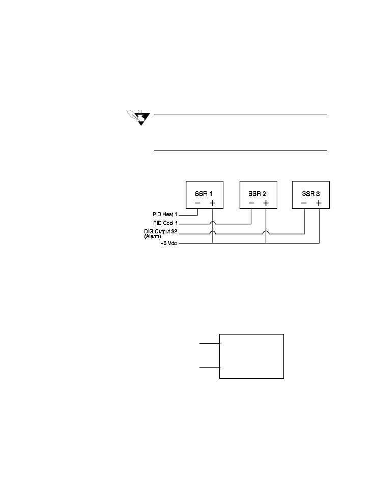
PID Control and Alarm Output Connections
Typical digital control outputs use external optically-isolated solid-state
relays (SSRs). The SSRs use a 3 to 32 Vdc input for control, and you
can size them to switch up to 100 amps at 480 Vac. For larger currents,
use these optically-isolated relays to drive contactors.
NOTE
Control outputs are sink outputs. They are Low
when the output is On. Connect them to the nega-
tive side of Solid State Relays.
The next figure shows sample heat/cool and alarm output connections.
System Safe (Watchdog Timer) constantly monitors the MLS CPU. It is
a SINK output located on RTB terminal #6. (Do not exceed the 10
mAdc rating for the System Safe output.) Its output is Low (on) when
the CPU is operating; when it stops operating, the output goes High
(off), de-energizing the SSR.
Here's the recommended circuit for the System Safe output:
SSR
+
_
+5 Vdc
(RTB pin 2)
System safe
(RTB pin 6)
- 12LS Controller (111 pages)
- 8LS Controller (140 pages)
- 8PID Controller (55 pages)
- Addendum to EZwarePlus (50 pages)
- ANASCAN (62 pages)
- ANASOFT (95 pages)
- ANAWIN 2 (154 pages)
- ANAWIN 3 (23 pages)
- Calibrating Watlow Series 988 Family Process Controls (19 pages)
- CAS (98 pages)
- CAS200 (124 pages)
- CLS (180 pages)
- CLS200 (251 pages)
- CLS200, MLS300 and CAS200 (92 pages)
- Control Console (12 pages)
- CPC400 (230 pages)
- DIN-A-MITE Style A (9 pages)
- DIN-A-MITE Style B (14 pages)
- DIN-A-MITE Style C (22 pages)
- DIN-A-MITE Style D (9 pages)
- DIN-Mount Adapter Instruction Sheet, Rev A (1 page)
- Dual DAC (4 pages)
- EM Gateway (28 pages)
- E-Safe Hybrid Relay Rev B (4 pages)
- E-SAFE II Hybrid Power Switch (4 pages)
- EZwarePlus Programming (264 pages)
- EZ-ZONE PM (111 pages)
- EZ-ZONE PM PID (125 pages)
- EZ-ZONE PM Express Limit (34 pages)
- EZ-ZONE PM Express (35 pages)
- EZ-ZONE PM Integrated Controller (181 pages)
- EZ-ZONE RM Limit Module Rev C (127 pages)
- EZ-ZONE RMA Modul (79 pages)
- EZ-ZONE RMC (236 pages)
- EZ-ZONE RME (124 pages)
- EZ-ZONE RMH (161 pages)
- EZ-ZONE RUI/Gateway (62 pages)
- EZ-ZONE RM-Scanner-Modul (140 pages)
- EZ-ZONE ST (97 pages)
- F4 External Event Board - Rev.B (2 pages)
- HG Series Mercury Displacement Relay (6 pages)
- LogicPro (296 pages)
- Mercury Relay or MDR Retrofit (13 pages)
- MICRODIN (24 pages)
- MICRODIN (106 pages)