Connecting thermocouples, Rtd inputs – Watlow MLS User Manual
Page 52
40 MLS User’s Guide
Installation
Connecting Thermocouples
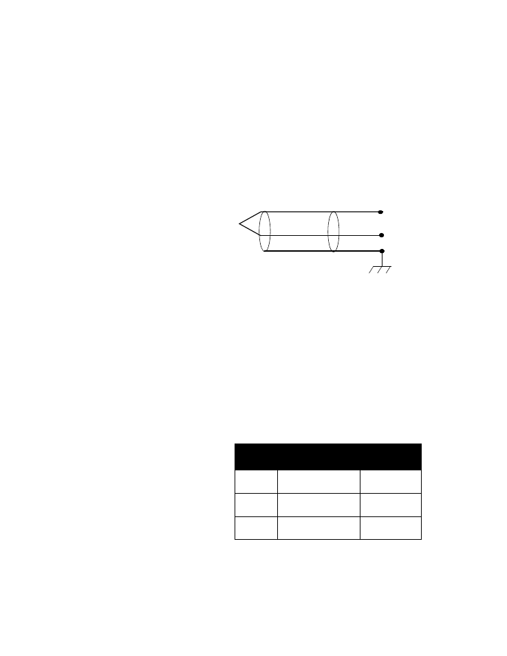
Connect the positive T/C lead to the A+ terminal. Connect the negative
T/C lead to the A- terminal of TB1. The figure below shows a typical
thermocouple connection.
•
Use 20 gauge T/C extension wire for all T/C inputs.
•
If you use shielded wire, tie the shield to panel ground.
•
Install a jumper or zero ohm resistor in location RC on the AIM-TB
if it had been removed.
This figure shows a typical thermocouple connection.
RTD Inputs
The standard industrial RTD is an 100 ohm, three-wire, platinum
assembly as shown in the next figure. Watlow-Anafaze highly
recommends that you use the three-wire RTD to prevent reading errors
due to cable resistance.
•
If you order an RTD1, RTD2, or RTD3 configuration, we will con-
figure your MLS for the standard three-wire RTD.
•
If you must use a two-wire RTD, jumper A- to AUX.
•
If you must use a four-wire RTD, do not connect the fourth wire.
Watlow-Anafaze offers three standard DIN 385 curve RTD input
ranges, as shown in the table below:
This figure shows a typical 3-wire RTD connection.
RTD
Type
Input Range
Display
Resolution
RTD1
-100.0 to 300.0 C
-148.0 to 572.0 F
0.1 C
0.1 F
RTD2
-120 to 840 C
-184 to 1544 F
1 C
1 F
RTD3
-70 to 300 C
-94 to 572 F
1 C
1 F
White
Red
Type J T/C
IN +
IN
–
Shield