Lincoln Electric IMt913 MAGNUM 100SG SPOOL GUN User Manual
Page 29
MAINTENANCE
D-4
4. Obtain a new replacement gun tube (if need-
ed). Remove locking nut from old gun tube and
install onto new gun tube. Nut should be fully
threaded finger-tight against the insulating
tube.
5. Slide gun tubeʼs external threads through gun
tube mounting plate and screw the gun tube by
hand into the cable connector until the nut pulls
the mounting plate snug against the connector.
6. Tighten the nut and mounting plate to the con-
nector with Torque Wrench 10 to 12 ft.-lbs.
7. Reassemble gun. Be careful not to pinch any
leads between gun handle halves.
WIRE DRIVE ASSEMBLY REMOVAL AND
INSTALLATION
1. There are no serviceable or maintainable parts
inside of the wire drive.
2. Remove liner assembly (See Maintenance
Section figures D.2 and D.3).
3. Remove left side of handle.
4. Disconnect black and red leads from drive
motor. Use care to prevent damage to motorʼs
fast-on electrical tabs.
5. Slide wire drive out of right handle half.
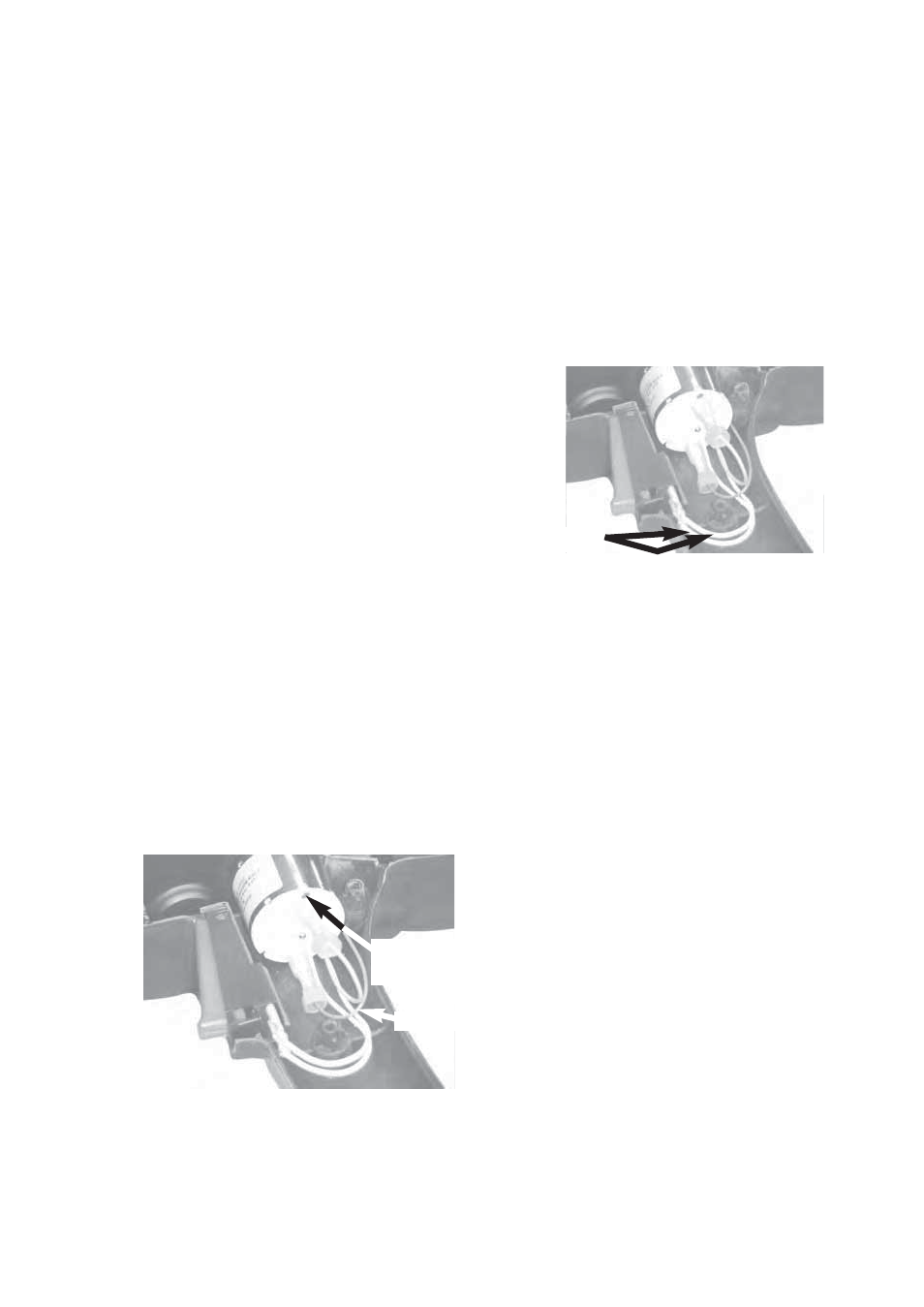
6. When reinstalling wire drive, note the proper
motor lead connection in the figure. Reconnect
red motor lead to positive (+) terminal, marked
with red dot at arrow. Reconnect black lead to
other motor terminal. (See figure D.11)
FIGURE D.11
7. Reassemble gun. Be careful not to pinch any
leads between gun handle halves.
TRIGGER ASSEMBLY REPLACEMENT
1. There are no serviceable or maintainable parts
inside of the trigger.
2. Remove spool cover and left side of handle.
3. Slide trigger out of right handle half. Disconnect
both white leads from trigger. Use care to pre-
vent damage to electrical leads and the termi-
nals. (See Figure D.12)
FIGURE D.12
4. Connect both white leads to the new trigger.
Either lead may be connected to either trigger
pin (non-polarized connections).
5. Slide new trigger into place and reassemble the
gun. Be careful not to pinch any leads between
gun handle halves.
WELDING CABLE ASSEMBLY
REPLACEMENT
1. Generally, there are no serviceable or maintain-
able parts, except for both o-rings on the
machineʼs power and gas connector; these
seals may be replaced. However, there are
options:
• Damage to the four #22 AWG control leads at
the gun cableʼs welding machine end (P6 plug)
may be repairable without
removing or
replacing the entire gun cable. The leads
can be spliced and soldered back togeth-
er, and then reinsulated with heat-shrink
tubing. See Table D.1 in Maintenance
Section for a description of the connec-
tions.
• Otherwise, the damaged gun cable may
be replaced.
White Leads
“+” Terminal
Red Dot
Black Lead