Safety precautions, Routine and periodic maintenance, Cleaning and inspections – Lincoln Electric IMt913 MAGNUM 100SG SPOOL GUN User Manual
Page 26: Maintenance d-1 warning p6 connector pin-out, Gas diffuser replacement
SAFETY PRECAUTIONS
ELECTRIC SHOCK can kill.
• Only qualified personnel
should perform this main-
tenance.
• Turn the input power OFF at the dis-
connect switch or fuse box before
working on this equipment.
• Do not touch electrically hot parts.
-----------------------------------------------------
ROUTINE AND PERIODIC
MAINTENANCE
RECOMMENDED TOOLS
• #2 Phillips screw-driver
• Slotted screw-driver
• 5/16 inch nut driver
• Torque Wrench
• Adjustable-jaw pliers
• 7/16 inch open-end wrench (gas diffuser)
• 9/16 inch open-end wrench (gun tube nut)
• Welding pliers (optional)
• Wire cutter
• Wire stripper
• Needle nose pliers
• Terminal crimping tool
• Flashlight
• Hand-held electrical meter *
• 3.0 mm metric allen wrench (drive roll
screw)
• Tape measure or 6-inch scale
• Tachometer (optional)
*Note: Two meters are used for simultaneously
measuring drive motorʼs voltage and current.
CLEANING AND INSPECTIONS
• Vacuum out any aluminum shavings that may
have accumulated inside of the gun. ( See
Correcting Wire Shaving Issues in this section).
• Wipe off dust and debris.
• Check that the gun tube and its lock nut are
properly tightened to the cable connector.
• Replace any warning or product identification
decals that have become illegible.
MAINTENANCE
D-1
WARNING
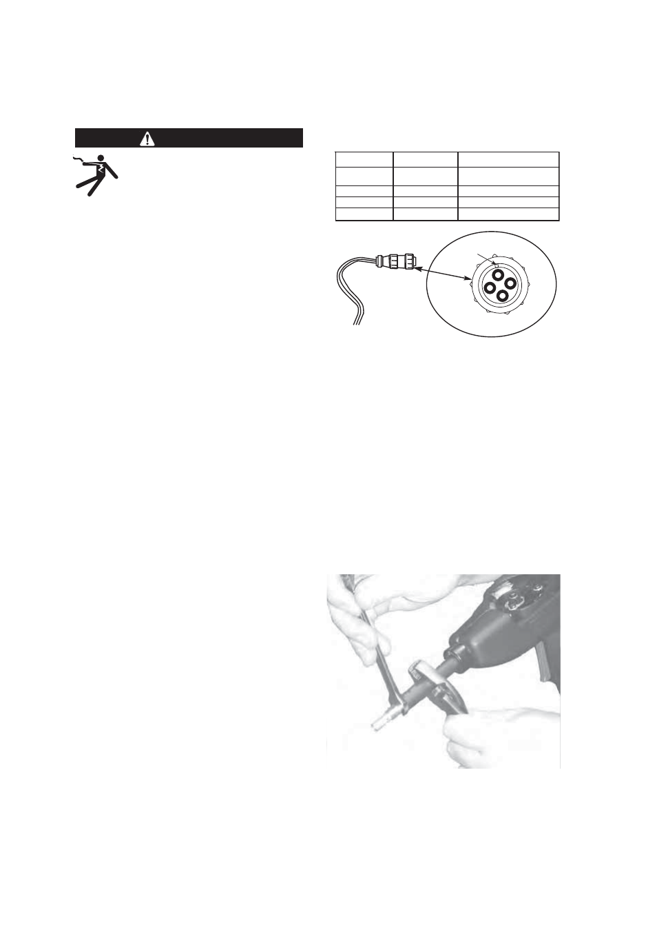
P6 CONNECTOR PIN-OUT
TABLE D.1
GAS DIFFUSER REPLACEMENT
This part may need to be replaced if it
has accumulated excessive spatter and
cannot be cleaned:
1. Remove gas cone and contact tip.
2. Carefully grasp gun tube with pliers
to prevent accidentally loosening gun
tube. Gas diffuser has right-hand
threads. Loosen gas diffuser with
wrench. (See Figure D.1)
FIGURE D.1
3. Install gas diffuser and thread into
place in gun tube. Tighten diffuser to
41 to 47 in.-lbs. with Torque Wrench.
Pin No.
1
2
3
4
Function
Trigger
Trigger
+ Motor
- Motor
Gun Cable Lead Color
White
White
Red
Black
1
2
2
4
3
P6 CONNECTOR PINOUT
MASTER KEY
Pin No.
1
2
3
4
Function
Trigger
Trigger
+ Motor
- Motor
Gun Cable Lead Color
White
White
Red
Black
1
2
2
4
3
P6 CONNECTOR PINOUT
MASTER KEY