Description – IEI Integration WAFER-LX v1.0 User Manual
Page 40
WAFER-LX
13. CN13: AT Power ON/OFF Button Connector
This connector is used to connect a chassis power On/Off button using an adapter cable.
This connector is closely related to JP1 configuration. The use of this connector is briefed as
follows:
1. Using
ATX power: CN13 connects to a power switch, and the JP1 jumper should be
left open.
2. Using
AT power:
The pins on JP1 are shorted by a jumper cap. The reason why
JP1 should be shorted is because the AMD Southbridge is
designed without the consideration for a power button signal and
the shorted JP1 provides a hardware feedback to initiate the
system.
Table 2-13
CN13 Power ON/OFF Button Connector Pinouts
PIN
DESCRIPTION
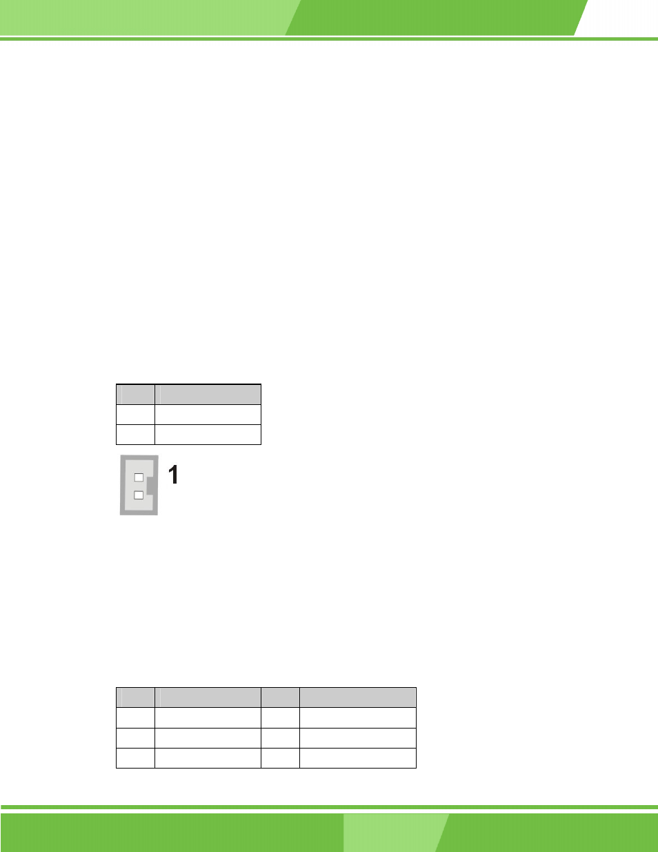
1
PWR_BTN#
2 GND
Figure 2-13 CN13 Power ON/OFF Button Connector
14. CN14: Digital I/O Connector
This Digital I/O port is managed through AMD CS5536AD Southbridge. The first table below
shows the CN14 port pinouts. The second table shows the Digital I/O port assembly codes.
Table 2-14
CN14 Digital I/O Connector Pinouts
PIN
DESCRIPTION
PIN
DESCRIPTION
1
GND 2
+5V
3 DIO_IN0
4 DIO_OUT0
5
DIO_IIN1 6
DIO_OUT1
2-19
2-19