Connectivity, Label, Function – IEI Integration WAFER-LX v1.0 User Manual
Page 14: Wafer-lx user manual
WAFER-LX User Manual
Connectivity
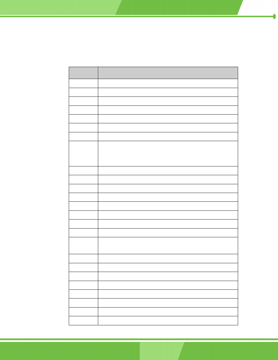
The WAFER-LX provides the following interface connections:
Label
Function
CN1
4P power connector
CN2
3-pin PS-ON/ATX feature connector
CN3
5-pin Inverter control
CN4
3-pin CPU fan connector
CN5
5-pin External LED connector (to chassis LED control PCB)
CN6
144-pin SDRAM SO-DIMM socket
CN7
2-pin connector to the external Lithium 3V coin cell battery-
CN8
10-pin audio connector (to the external adapter cable kit which
should provide phone jacks for Line_out, Line_in, and MIC_in
connectivity)
CN9
4-pin Audio CD_IN connector
CN10
PC/104 connector (104-pin ISA bus)
CN11
3-pin external VCC (supplementary for PC/104) power connector
CN12
2-pin Reset button switch (to the chassis front panel)
CN13
2-pin Power switch button (to the chassis front panel)
CN14
10-pin general purpose I/Os connector
CN15
26-pin parallel port pin header
CN16
14-pin internal serial port pin header (COM2)
CN17
6-pin keyboard/mouse connector (a 6-pin-to-PS/2 adapter cable is
required)
CN18
Not implemented
CN19
External USB1.1 connector (2 ports)
CN20
10/100BaseT Ethernet port
CN21
10/100BaseT Ethernet port
CN22
External D-SUB 9 serial port connector (COM1)
CN23
Serial ATA connector
CN24
8-pin internal USB header (an adapter cable required)
CN25
Serial ATA connector
1-4
1-4
IEI
®
Technology, Corp.