IEI Integration WAFER-LX v1.0 User Manual
Page 33
WAFER-LX User Manual
1x3 WAFER 2mm connector.
Using CN2 as a Power Feature Connector:
The SBVCC connector can support an advanced soft power switch function. If an
ATX power supply is used, connect an ATX-to-4P power cable between the SBVCC connector
and ATX power source. Also connect a power on/off switch to the ATX ON/OFF switch
previously mentioned. Note that your ATX power supply should provide a 10mA load on the
5V source standby lead for this function to take effect.
IEI provides an ATX-to-4P adapter cable that comes with a 20-pin ATX connector, a 3-pin
connector to the SBVCC (CN2) connector, and a 4P power connector. This board uses an
adapter cable different from that provided with the previous WAFER models, please
refer to Appendix B for more information.
Using CN2 as a Configuration Jumper:
A jumper cap is installed on pins 1 and 2 as factory default (pin1=+5VSB; pin2=+5V). If the
WAFER-LX is connected to an AT power, let the jumper stay on pins 1 and 2. If connected to
an ATX power source, remove the jumper cap.
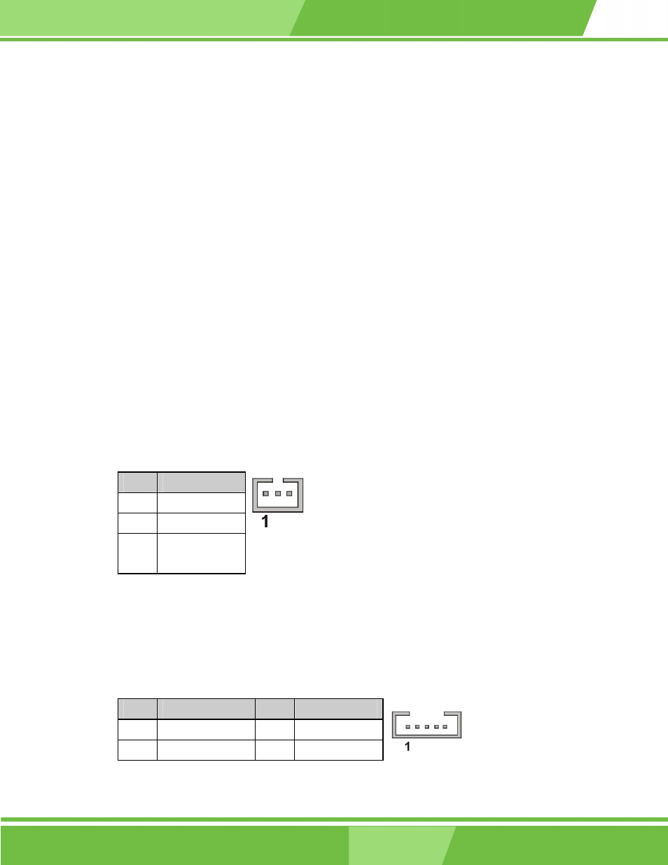
Table 2-4 CN2 SBVCC: ATX Power Feature Pinouts
PIN
DESCRIPTION
1 5VSB
2 +5V
3 GND
Figure 2-6 CN2 SBVCC ATX Power Feature
3. CN3: IVTC LCD Panel Inverter Backlight Control Connector
This connector comes as a 1x5 pin Wafer 2mm connector.
Table 2-5 CN3 IVTC Inverter Control Pinouts
PIN
DESCRIPTION
PIN
DESCRIPTION
1 VCC12 2
GROUND
3 VEEON 4 BLADJ
2-12
2-12
IEI
®
Technology, Corp.