3 so-dimm installation, So-dimm, Nstallation – IEI Integration KINO-CV-D25501_N26001 User Manual
Page 63: Figure 4-1: so-dimm installation
KINO-CV-D25501/N26001 SBC
Page 49
Before and during the installation of the KINO-CV-D25501/N26001 DO NOT:
DO NOT remove any of the stickers on the PCB board. These stickers are
required for warranty validation.
DO NOT use the product before verifying all the cables and power connectors
are properly connected.
DO NOT allow screws to come in contact with the PCB circuit, connector pins,
or its components.
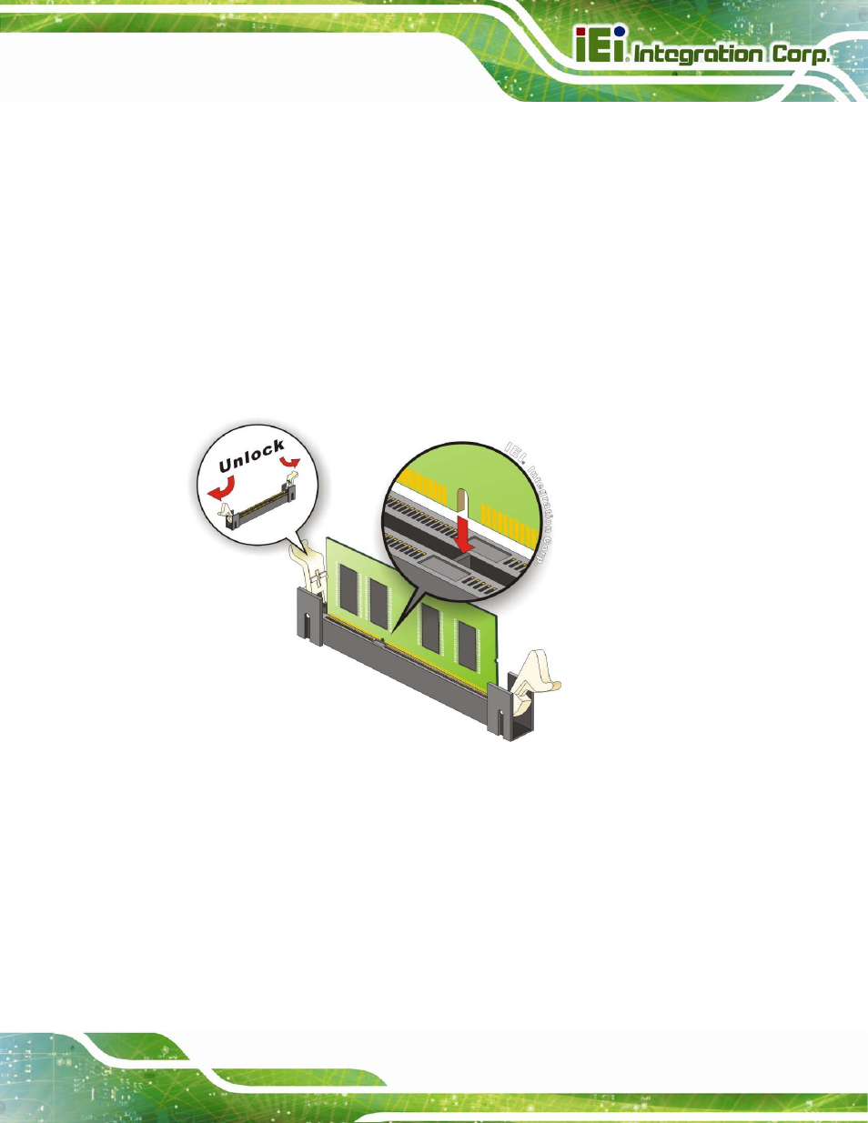
4.3 SO-DIMM Installation
To install a SO-DIMM, please follow the steps below and refer to Figure 4-1.
Figure 4-1: SO-DIMM Installation
Step 1:
Open the SO-DIMM socket handles. Open the two handles outwards as far as
they can. See Figure 4-1.
Step 2:
Align the SO-DIMM with the socket. Align the SO-DIMM so the notch on the
memory lines up with the notch on the memory socket. See Figure 4-1.
Step 3:
Insert the SO-DIMM. Once aligned, press down until the SO-DIMM is properly
seated. Clip the two handles into place. See Figure 4-1.