IEI Integration SPCIE-5100DX User Manual
Page 73
SPCIE-5100DX PICMG 1.3 CPU Card
Page 59
4-14.
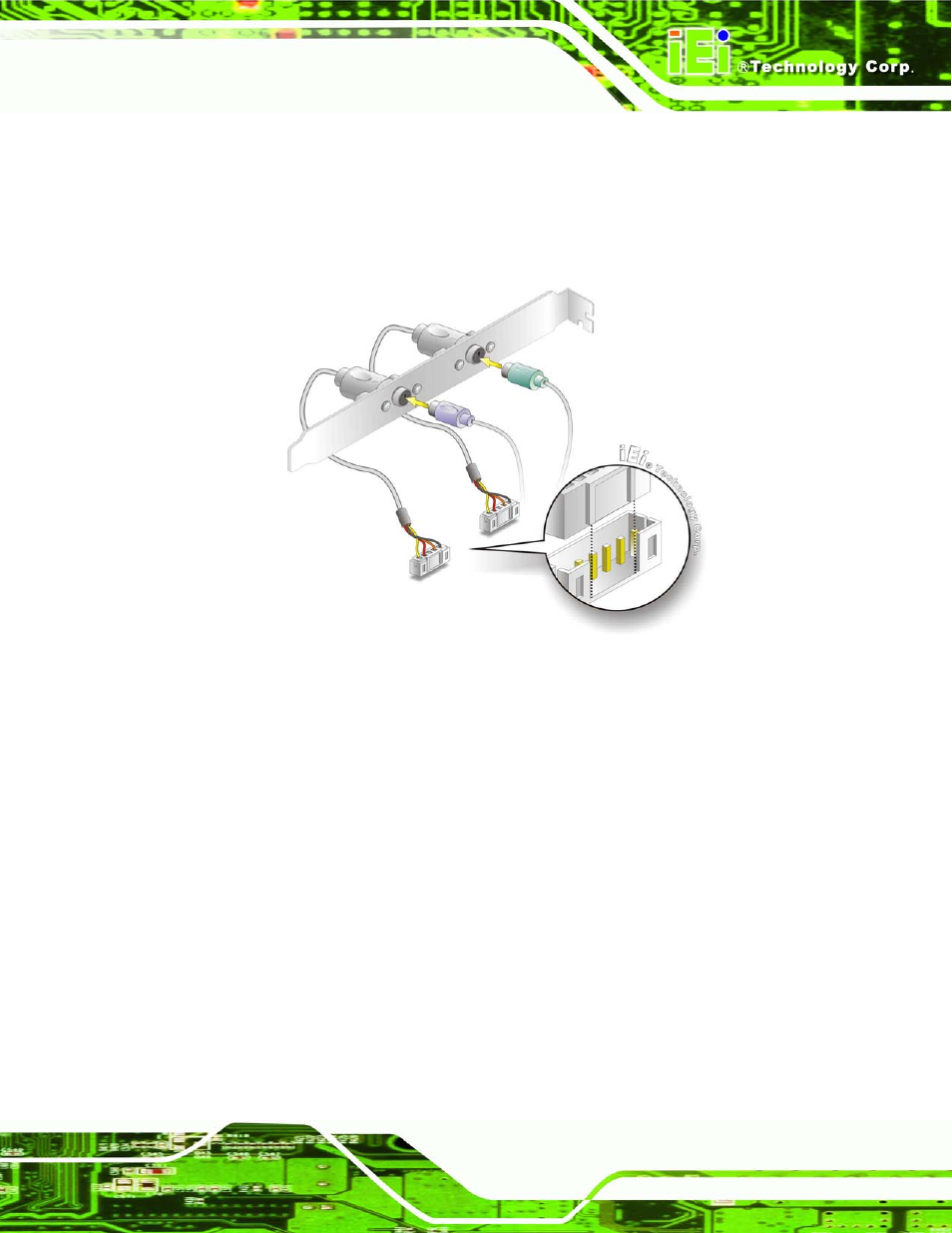
Step 3:
Insert the cable connectors. Once the keyboard (mouse) cable connector is
properly aligned with the keyboard (mouse) connector on the SPCIE-5100DX,
connect the cable connector to the on-board connector. See Figure 4-14.
Figure 4-14: Keyboard and Mouse PS/2 Cable with Bracket
Step 4:
Connect the bracket to the chassis. The bracket has a retention screw hole at
the top. Properly insert the bracket into the chassis and secure the bracket to the
chassis with a retention screw passing through the retention screw hole. Please
see the chassis installation instructions for more details.
Step 5:
Connect the keyboard and mouse. Once the PS/2 connectors are connected to
the chassis, a keyboard and mouse can each be connected to one of the PS/2
connectors. See Figure 4-14.The keyboard PS/2 connector and mouse PS/2
connector are both marked. Please make sure the keyboard and mouse are
connected to the correct PS/2 connector.
Step 0: