Receiver test case block – Teledyne LeCroy PeRT3 Eagle Systems User Manual
Page 47
PeRT
3
Eagle User Manual
Version 1.6
LeCroy Corporation
43
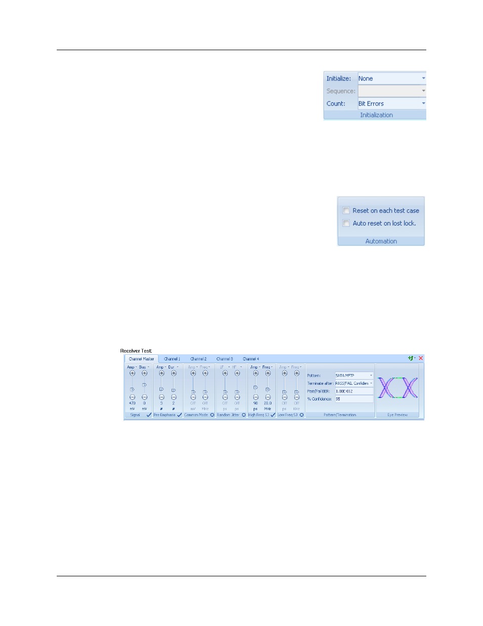
Initialization
The Initialization panel allows the user to select an
initialization command sequence. The options displayed
here are dependent on the protocol selected, but
typically include Loopback, Frame Level, Custom or
None. Loopback will place the DUT into a loopback
mode for testing. If no standard "enter loopback test mode" command exists in that
protocol, but the device vendor supports a custom command, that command can be
entered using the Pattern Editor (see “Creating Test Patterns” on page 45) and then
selected from the drop-down menu of existing patterns in the Sequence field of this
panel. This also allows the testing to change between bit level errors and frame level
errors by selecting the desired method from the Count drop-down menu.
Automation
The Automation panel allows the user to specify reset
conditions that might be required during automated testing.
Reset on each test case will force a reset each time a new
test case begins, and Auto reset on lost lock will reset the
system and attempt to recover lock when lost.
Receiver Test Case Block
The Receiver Test block contains tabs across the top corresponding to channels
supported by the system. The Channel Master tab controls all channels (if using a single
channel system, there will be no Channel Master tab, only the Channel 1 tab will be
shown). Click on a specific channel tab to select any of the channels to be tested (limited
by the number of channels defined in the Test Script Data Panel).
Selecting any of
these tabs allows the user to specify the test conditions for that specific channel.
Test conditions for channels are defined in exactly the same way as previously outlined
under Manual Testing, see “System Control Ribbon -- Channel Tabs” on page 25.
A single Receiver Test block can be used to test all channels simultaneously by
specifying the same (or different) test conditions for each channel, or each channel may
be tested in sequence by adding additional Receiver Test blocks and defining a test for
only one channel in each Receiver Test block.
When defining test conditions, the Eye Diagram panel serves as a guide to the level of
signal impairment being introduced by the conditions specified in this specific test case.