Relay and open collector wiring – GF Signet 9900-1BC Batch Controller System User Manual
Page 9
9
9900-1BC Batch Controller Manual
Relay and Open Collector Wiring
The 9900 Open Collector (R1) output provides high-speed switching capability. Signal frequencies can reach
400 pulses per minute.
The 9900 Open Collector (R1) output connection is dependent upon the type of circuit being controlled by the output.
Most indicating instruments or control system inputs require a signal voltage of 0 to 5 V (TTL or CMOS logic levels)
or 0 to 24 V. Therefore, the 9900 Open Collector output circuits must be equipped with a pull-up or pull-down
resistor (not supplied), and a quality regulated 5 to 24 V (depending on the application) power supply (not supplied)
is recommended to function properly.
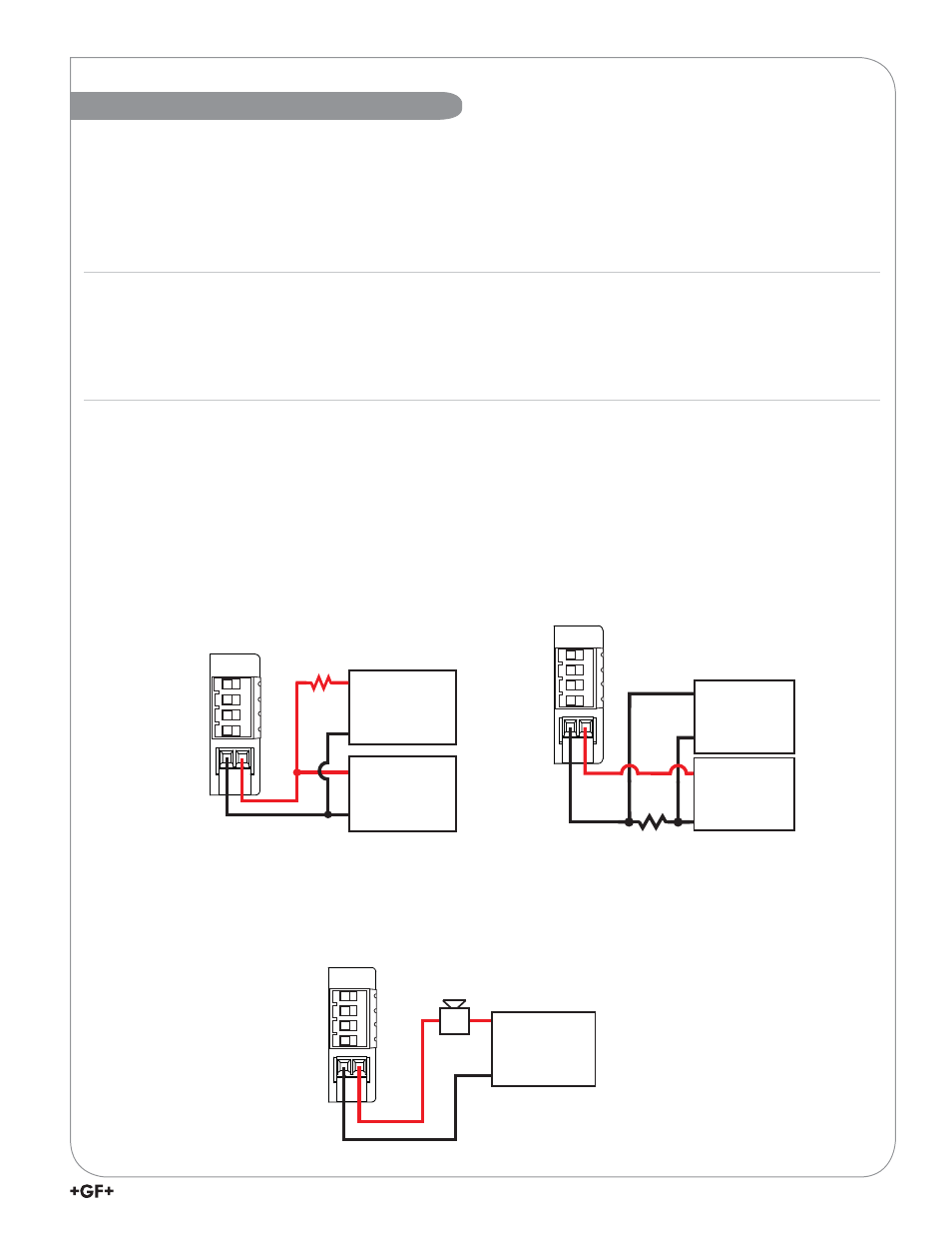
Open Collector Wiring
PWR +
PWR –
Loop +
Loop –
OC –
OC +
Power
Supply
V+
Gnd
Alarm
with NORMAL
set to OPEN.
If an external device needs logic 0
(logic LOW) input when the Open
Collector is de-energized in an NPN
confi guration, set R1 NORMAL to
CLOSED in the RELAY menu.
PWR +
PWR –
Loop +
Loop –
OC –
OC +
Pull-Up Resistor
..ȍ:
Power
Supply
9WR9
Gnd
PLC
Gnd
Input
NPN Style Wiring
OC +
Pull-Down Resistor
..ȍ:
Power
Supply
9WR9
Gnd
PLC
Gnd
Input
3:5
3:5±
Loop +
/RRS±
2&±
PNP Style Wiring
• Longer life than a mechanical relay
• No moving parts
• Faster ON/OFF switching capabilities than mechanical relays
• Can switch DC voltage only (< 30 VDC, < 50 mA)
• Not recommended for use with inductive loads
Fail-Safe Behavior
No matter the setting, the Open Collector output turns off if the 9900 loses power. This must be taken into account
when evaluating system failure consequences. If the system layout requires a “closed” or “on” condition for the
output in case of power loss, a mechanical dry-contact relay (NC contacts) must be used instead of the Open
Collector (R1) output.