Sensor wiring – GF Signet 9900-1BC Batch Controller System User Manual
Page 7
7
9900-1BC Batch Controller Manual
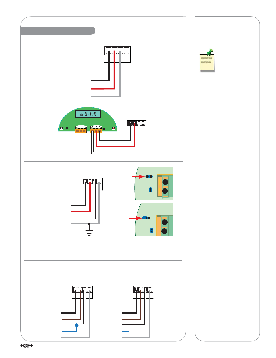
Sensor Wiring
2551 Technical Notes:
• When the blue jumper
illustrated is placed over
both pins, the 2551-XX-
11 (Blind Magmeter)
outputs an open collector
frequency signal. When
the jumper is removed (or
placed over one pin for
storage) the
2551-XX-11 outputs a
Digital (S
3
L) signal.
2551 & 2552
Technical Notes:
• Either Frequency or
Digital (S
3
L) may
be used.
• The frequency output will
be displayed as positive
fl ow regardless of the fl ow
direction.
• Signet recommends
confi guring the 2551
with the Digital (S
3
L)
output because it is more
accurate.
• Input sensor type is
selected by choosing
between “SENSOR FREQ”
and "SENSOR S3L" in the
INPUT menu.
• 5 VDC power is provided
to the 2551 Magmeter by
the
9900-1BC. No additional
power is required.
DA
T
A
GND
SHLD
V+
Black
Red
Shield
No connection
DA
T
A
GND
SHLD
V+
Brown
White
Blue
Black
Shield
S
3
L
DA
T
A
GND
SHLD
V+
Brown
White
Blue
Black
Shield
X
No
connection
Frequency
S1
S2
Blk
Red Shld
-
+
DA
TA
GND
SHLD
V+
Black
Red
White
No connection
Black
Red
Shield
White
V+
DA
T
A
GND
SHLD
3
4
Frequency
S L
3
3
4
515 (8510), 525,
2000, 2100, 2507,
2536 (8512), 2540
2551*
2537
2552
*2551 Blind Magmeter
Output Selection Jumpers
Connect the silver (shield)
wire to earth ground in case
of EMI noise interference.