Burkert Type 2100 User Manual
Page 30
30
Maintenance, cleaning
Series production status up to January 2013
→
Unscrew the spindle guide with the aid of the installation
wrench
7)
and an open-end wrench.
Series production status since January
→
Unscrew the spindle guide with the aid of a modified socket
wrench
7)
.
WARNING!
Risk of injury from parts jumping out!
When the spindle opening is exposed, the individual parts of the
packing gland are pressed out at an undefined speed when the
pilot air ports is pressurized.
• Before pressurizing with control air, safeguard the ambient area
of the discharge opening (e.g. place spindle on a firm base).
→
Control function A and I Pressurize pilot air port 1 with 6 – 8
bar (see “Fig. 22: Designation parts”).
→
Control function B Pressurize pilot air port 2 with 6 – 8 bar (see
“Fig. 22: Designation parts”).
→
Grease the individual parts of the new packing gland with the
upplied lubricant.
→
Connect the individual parts to the spindle in the specified
direction and sequence (as illustrated in “Fig. 26”).
7)
The installation wrench or modified socket wrench is available
from your Bürkert sales office.
→
Push packing gland into the packing gland tube.
→
Screw spindle guide back in using the installation tool. Observe
torque (see “Tab. 7”)
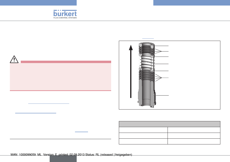
Support ring
Upper chevron seals
Upper pressure ring
Pressure spring
Lower pressure ring
Lower chevron seals
Spindle guide
Insertion direction
for packing gland parts
Fig. 26: Seal set for packing gland
Tightening torques of spindle
Spindle diameter
Tightening torque [Nm]
10 mm
6
14 mm
15
Tab. 7: Tightening torques of spindle
english
Type 2100