2 bus termination in connection cap – BEI Sensors MHK5 Absolute Hollow Shaft Encoder User Manual
Page 8
Version 07/10
BEI Sensors CANopen Manual serie M
8
ON
T
R
T
ON
R
Bus In
Bus Out
G
G
+
-
L
H
R
ON
T
L
H
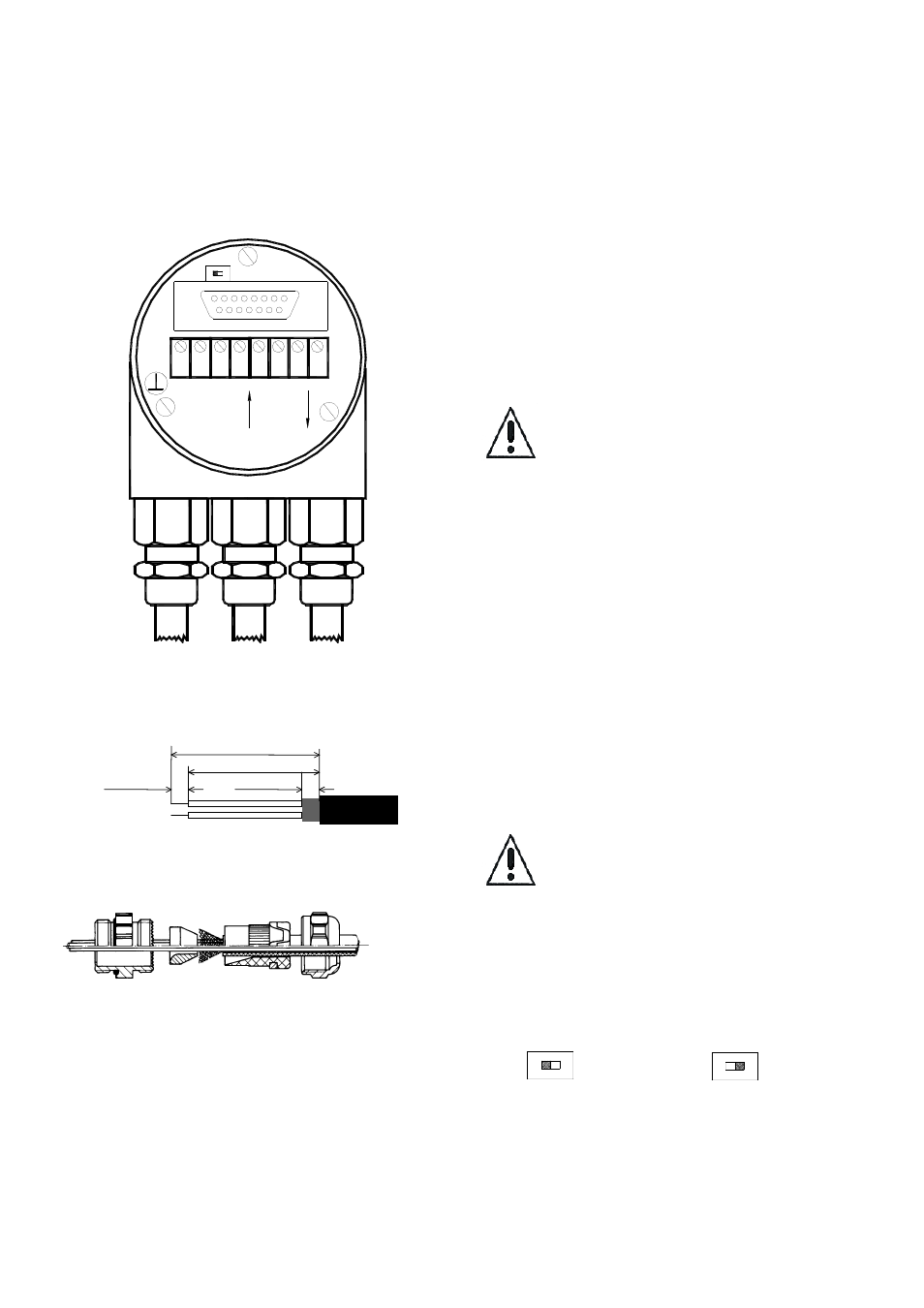
Bus Connection
The connection cap fulfills the function of a T-
coupler. From there the wiring must be done
according to the drawing on the left side. Please
note the assignment of incoming and outgoing bus
signals.
An activated bus termination
resistor will lead into a separation
of bus in and bus out signals!
Cable Connection
Remove screw, sealing and cone from the cable
gland. Remove 55 mm of the sheath and 50 mm of
the shielding. About 5 mm of the wires should be
de-isolated. Put screw, and sealing on the cable.
The cone should be mounted under the shielding
according to the figure 3. Put the whole cable into
the cable gland and tighten the screw.
2.1.2 Bus Termination in Connection Cap
If the encoder is connected at the end or beginning
of the bus the termination resistor must be
switched on. The termination resistor is switched
on when the switch is in the ON position.
Separation of Bus In and Bus Out
signals if termination resistor is
activated.
There is a resistor provided in the connection cap,
which must be used as a line termination on the
last device.
Resistor:
Last Device
Device X
Fig. 1 Connection cap bus in and bus out
Fig. 2 Cable preparation
Fig. 3 Cable connection
5 mm
5 mm
55 mm
50 mm