BEI Sensors HS35 Express Encoder User Manual
Hs35 absolute encoder ordering options, Hs35 absolute encoder, Electrical specifications
Tel: 805-968-0782 /800-350-2727 | Fax: 805-968-3154 / 800-960-2726
7230 Hollister Ave., Goleta, CA 93117-2807 |
www.beisensors.com
Specification No. 02070-001 Rev.07-12
These commodities, technology or software if exported from the United States must be in accordance with the Bureau of Industry, and Security, Export Administration regulations. Diversion contrary to U.S law is prohibited.
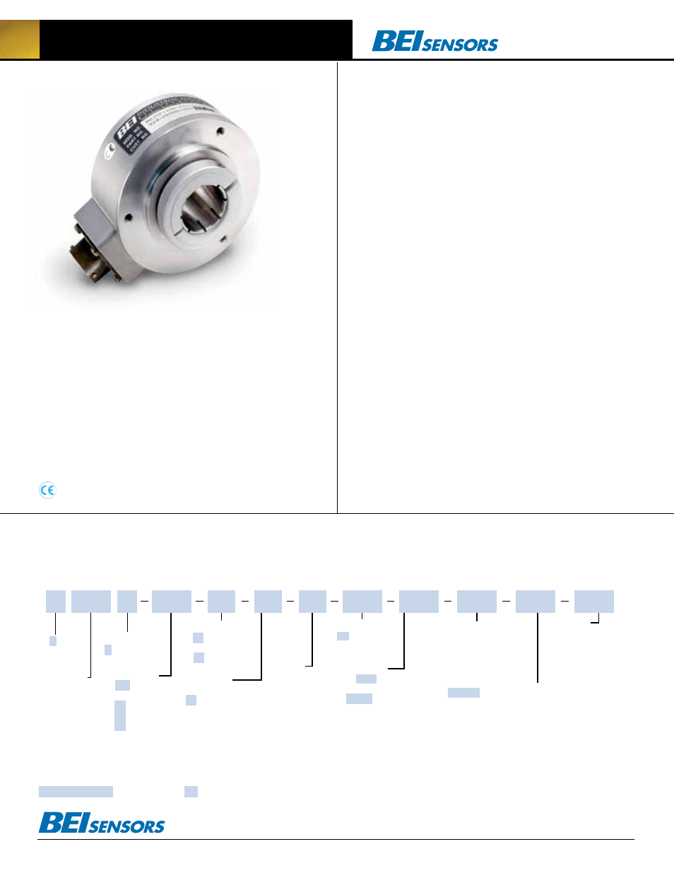
HS35 Absolute Encoder
Built on the same rugged design as the incremental model, the HS35
Absolute Encoder is available with various output options including
Gray Code and Natural Binary. Designed with a cast aluminum hous-
ing, a sealed connector and shaft seals, it carries an IP65 environ-
mental rating. With the optional insulating inserts, it can be mounted
on smaller diameter shafts. It is designed for either a through shaft
mounting or blind shaft mounting with a closed cover to maintain its
environmental rating.
Electrical Specifications
Code: 12 or 13 bits NB or GC
Counts Per Shaft Turn: 4096 or 8192 (with S3 option only)
Count Transition Accuracy: ± 1/2 bit maximum
Supply Voltage: 5–28 VDC
Current Requirements: 120 mA typical
Output Formats: Parallel: Gray Code, Natural Binary
Voltage/Output: (see note 2)
28V/V: Line Driver, 5–28 VDC in, Vout = Vin
28V/5: Line Driver, 5–28 VDC in, Vout = 5 VDC
28V/OC: Open Collector, 5–28 VDC in, OCout
SSI: 5–28 VDC in/5Vout (consult factory for more information)
Protection Level: Reverse, overvoltage and output short circuit protection
Frequency Response: 100kHz (1200 RPM for 12-bits)
Output Termination Pinouts: see tables, back page
Mechanical & Environmental Specs
Shaft Bore: 1.000, 0.875, 0.750, 0.625, 0.500. Diameters under 0.875 are supplied
with insulated sleeves.
Allowable Misalignment: 0.005” T.I.R. on mating shaft 0.75” from shaft end
Bore Runout: 0.001 T.I.R. maximum
Starting Torque at 25°C: Through shaft version (SS) = 7 in-oz (max);
Blind shaft version (BS) = 4 in-oz max
Bearings: 52100 SAE High carbon steel
Shaft Material: 416 Stainless Steel
Bearing Housing: Die cast aluminum with protective finish
Cover: Die cast aluminum with protective finish
Bearing Life: 7.5 X 10
9
revs (50,000 hours @ 2500 RPM)
Maximum RPM: 6,000 mechanical (see frequency response, above)
Moment of Inertia: 0.019 oz-in-sec
2
Weight: 18oz typical
Connector
MS3112E14-19P, 19–pin connector on encoder body, mates to MS3116J14-19S (or equivalent)
NOTES & TABLES: All notes and tables referred to in the text can be found on the
back of this page.
The H25 Incremental Encoder is avail able with the following certification:
EN 55011 and EN 61000-6-2
NuMBER
OF BITS:
12 = 12 Bits,
4096 counts
13 = 13 Bits,
8192 counts
(with S3
option only)
HOuSING :
F = Standard
HS35 Absolute Encoder Ordering Options
FoR ASSiSTANCe CAll
800-350-2727
Use this diagram, working from left to right to construct your model number (example:
HS35F-100-R1-SS-12GC-28V/V-CW-SM14/19).
All notes and tables referred to can be found on the back of this page.
TYPE:
HS = Hollow Shaft
35 = 3.5” Encoder
Diameter
SHAFT SEAL
CONFIGuRATION:
SS = Through Shaft
Rubber Seals
BS = Blind Shaft
Rubber Seal
FS = Through Shaft
Felt Seals
BFS = Blind Shaft Felt Seal
See note 1
OuTPuT TERMINATION:
SM14/19 = 19 Pin connector;
SCS = Shielded/Jacketed
Cable with Cable Seal. Length of Cable is
specified in inches (i.e. SCS18 = 18 inches)
M18 = MS3102R18-1P
(A1, A2 and S3 output only)
(
Consult factory for
more information)
TETHER:
R1 = Tether Block
and Pin
R2 = Tether Arm
COdE TYPE:
GC = Gray Code
NB = Natural Binary
dIRECTION OF COuNT:
CW = Clockwise
increasing count
CCW = Counter clockwise
increasing count
SPECIAL
FEATuRES:
S = Special
features specified on
purchase order
See note 3
(consult factory
for more
information)
HS35
SHAFT BORE:
100 = 1.00”
87 = 0.875”
75 = 0.75”
62 = 0.625”
50 = 0.50” etc
VOLTAGE/OuTPuT:
28V/V = 5-28Vin/out
28V/5 = 5-28Vin/5Vout
28V/OC = 5-28Vin/OCout
A1 = 4-20mA
A2 = 0-10V
S3 = Serial Synchronous Interface
See note 2
(consult factory for more information)
X =
Express
Encoder
EXPRESS ENCOdERS: Items highlighted with are standard Express Encoders and ship in one to three days.