BEI Sensors H38 Absolute Explosion Proof Encoder User Manual
H38 absolute encoder ordering options, H38 absolute explosion-proof encoder, Electrical specifications
Tel: 805-968-0782 /800-350-2727 | Fax: 805-968-3154 / 800-960-2726
7230 Hollister Ave., Goleta, CA 93117-2807 |
www.beisensors.com
Specification No. 02051-002 Rev.08-11
These commodities, technology or software if exported from the United States must be in accordance with the Bureau of Industry, and Security, Export Administration regulations. Diversion contrary to U.S law is prohibited.
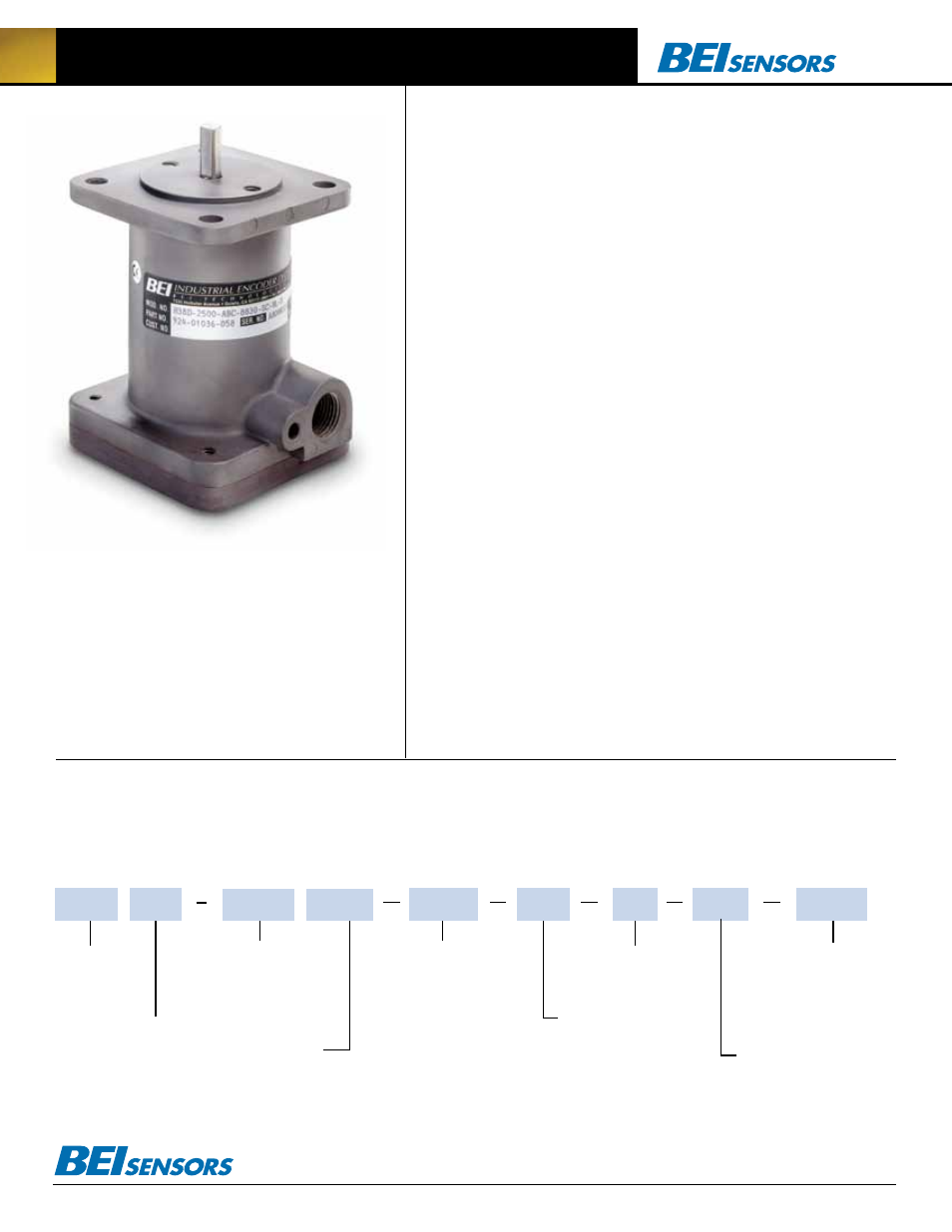
H38 Absolute Explosion-Proof Encoder
This is the same Explosion Proof rated encoder as the
H38 Incremental, in an absolute encoder version with
output up to 13 bits of resolution. When your application
needs the ability to recover position information quickly
after a power loss and you are operating in a hazardous
area—the H38 may be the answer to your needs.
Electrical
Specifications
Code: 12 or 13 bits NB or GC; excess gray
and BCD available
Counts Per Shaft Turn: 4096 or 8192
Count Transition Accuracy:
± 1/2 bit maximum
Supply Voltage: 5–28 VDC
Current Requirements: 120 mA typical
Output Formats: Parallel: Gray Code,
Natural Binary and Binary Coded Decimal;
Serial: Serial Synchronous Interface (SSI);
Analog: 4–20 mA, 0–10V
Voltage/Output: (see note 5)
28V/V: Line Driver, 5–28 VDC in, Vout = Vin
28V/5: Line Driver, 5–28 VDC in, Vout = 5 VDC
28V/OC: Open Collector, 5–28 VDC in OCout
SSI: 5–28 VDC in/5Vout
Protection Level: Reverse, overvoltage and
output short circuit protection
Frequency Response: 100kHz (1200 RPM for
12-bits, 600 RPM for 13-bits)
Output Termination Pinouts:
See table 3, back page
Mechanical
Specifications
Shaft Diameter: 3/8” nominal
Flats On Shaft: Two flats, 0.80” long X 0.30”
deep at 90º
Shaft Loading: Up to 40 pounds axial and 20
pounds radial applied 1/4” from housing
Shaft Runout: 0.0005 T.I.R.
Starting Torque at 25° C: 4.0 in-oz (max)
Bearings: Class ABEC 7 standard
Shaft Material: 303 stainless steel
Enclosure: Die cast aluminum, hard anodized
with dichromate sealed finish. Shaft seals
and sealed bearings are standard to achieve
environmental ratings.
Bearing Life: 2 X 10
8
revs (1300 hrs at 2500
RPM) at rated load; 1 X 10
10
revs (67,000 hrs at
2500 RPM) at 10% of rated load
Maximum RPM: 10,000 RPM (see frequency
response, below)
Moment of Inertia: 4.1 X 10
–4
oz-in-sec
2
Weight: 64 oz typical (approx 4 lbs)
Environmental
Specifications
Enclosure Rating: NEMA 4 X & 6 (IP66), out-
door Non-Hazardous locations, NEMA 4 X & 13
(IP66), indoor Non-Hazardous locations
Temperature: Operating, 0º to 70º C;
extended temperature testing available (see
note 8, pg 64); 80º C max for UL and CEN
approved units; storage; -25º to 90º C.
Shock: 50 g’s at 11 msec
Vibration: 5 to 2000 Hz @ 20 g’s
Humidity: 100% RH
Hazardous Area Rating: Underwriters
Laboratories listed for use in hazardous
locations; NEMA Enclosure 7. Class 1,
Group C & D, Division 1, NEC Class 2
circuits only, or Class 2, Groups E, F,
and G (see Table 1)
NOTES & TABLES: All notes and tables
referred to in the text can be found on the
back of this page.
CODE TYPE:
GC = Gray Code
NB = Natural Binary
BCD = Binary Coded Decimal
X = Excess gray code
HOUSING
CONFIGURATION:
D = Standard
H38 Absolute Encoder Ordering Options
FoR ASSiSTANCe CAll
800-350-2727
Use this diagram, working from left to right to construct your model number (example:
H38D-12GC-28V/V-CW-SC-UL).
All notes and tables referred to can be found onthe back of this page.
TYPE:
H = Heavy Duty;
38 = 3.75”
Square
NUMBER OF BITS:
12 = 12-Bits, 4096 counts per turn
13 = 13 Bits, 8192 counts per turn
14, 15, bits and HMT—Consult factory
(Excess gray codes and BCD
available–consult factory)
CERTIFICATION:
UL = Class I Group D Environments
CEN = UL Class I & II, Cenelec IIB Environments
VOLTAGE/OUTPUT:
28V/V = 5-28Vin/out
28V/5 = 5-28Vin/5Vout
28V/OC = 5-28Vin/OCout
A1 =4-20mA
A2 =0-10V
S1 = RS422 Asynchronous
Serial Interface
S3 =Serial Synchronous
Interface
(See note 5 and page 46 of the
2008 BEI Specifying Guide for SSI)
OUTPUT TERMINATION:
SC = Side Conduit, 1/2–14 NPSF
(dryseal) straight pipe threads
DIRECTION
OF COUNT:
CW = Clockwise
increasing count
CCW = Counter
clockwise increasing
count
SPECIAL FEATURES:
S = Special features specified
on purchase order
(consult factory)
See note 6
H38