Digital output – Extron Electronics IPL T SFI244 User Manual
Page 26
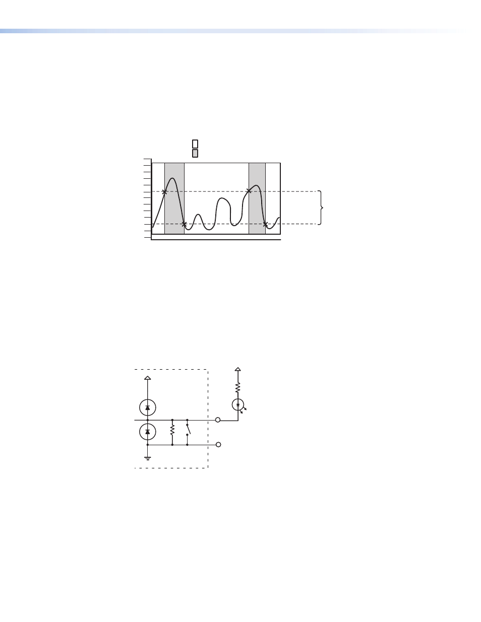
If the integrator selects threshold voltages that are more than 0.1 V apart, a deadband, or
hysteresis, will be established.
In the following example, the lower threshold voltage is set at +6 VDC and the upper
threshold is set at +16 VDC. The shaded bands show state changes on the logical
outputs.
The range between 6-16 VDC is the deadband in which the signal can fluctuate without
affecting the input state.
2
4
6
8
10
12
14
16
18
20
22
24
26
Low
High
Time
VDC
Upper
Hysteresis
Threshold
Lower
Threshold
Figure 18.
High and Low Transitions of Adjustable Threshold with Deadband
(Hysteresis)
Digital output
When a flex I/O port is configured as a digital output, it offers two output states: “on”
and “off”. When the port is set to an “on” state, (SW1 is closed), the I/O pin is connected
to ground (each I/O port is capable of sinking 250 mA max). When the port is set to the
“off” state, (SW1 is open), the output pin is floating.
If the application calls for TTL compatibility, SW2 can be selected to provide a 2K pull-up
resistor to +5 VDC.
I/O
24K
SW1
390
+30V
+5V
GND
Figure 19.
Sample of a Digital Output Port Driving an LED Using an External
+5 VDC Source
IPL T SFI244 • Communication and Control
20