Digital input – Extron Electronics IPL T SFI244 User Manual
Page 25
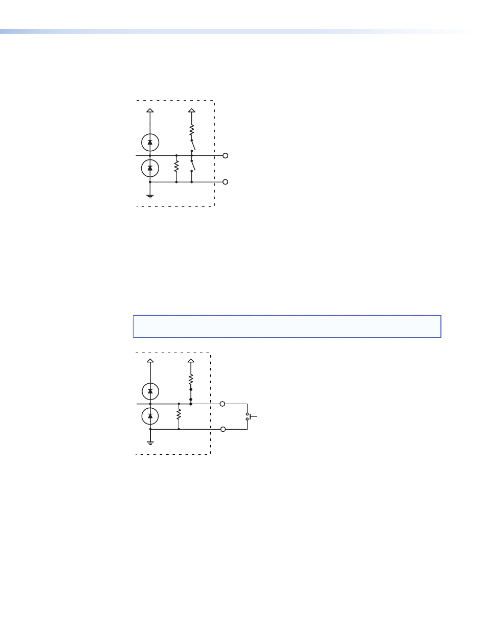
Digital input
When a flex I/O port is configured as a digital input, the port measures two states: 1 or 0;
On or Off; high or low. A closed circuit = a logic 1 and an open circuit = a logic 0.
24K
SW1
2K
+30V
+5V
SW2
I/O
GND
Figure 16.
Equivalent Digital Input Circuit
The Digital Input mode has two configurable options:
1.
The ability to turn on an internal pull-up resistor to +5 VDC (shown below as SW2)
2.
Adjustable detection threshold voltages
The default threshold voltages follow standard TTL logic: a voltage below 0.8 VDC is
measured as logic low and a voltage above 2.0 VDC is measured as logic high. Using an
adjustable threshold, the integrator can select the proper high and low voltages for the
installation.
NOTE: In the figure below, the SW2 switch is turned closed, activating the +5 VDC and
2K pull-up resistor.
I/O
2K
+30V
+5V
SW2
GND
24K
Figure 17.
Sample Wiring for a Digital Input Reading an External Pushbutton
Switch
IPL T SFI244 • Communication and Control
19
- Annotator 300 (4 pages)
- Annotator and USP 507 Output Boards (2 pages)
- Annotator Setup Guide (4 pages)
- Annotator User Guide (108 pages)
- CCR-4BLB AAP (1 page)
- CCR 204 4-User (1 page)
- CIA100 (14 pages)
- CIA101 (14 pages)
- CIA112 (18 pages)
- CIA116 (18 pages)
- CTL101 (34 pages)
- DMP 64 User Guide (146 pages)
- DMP 64 Setup Guide (2 pages)
- DMP 44 LC User Guide (81 pages)
- DMP 44 LC Setup Guide (2 pages)
- DMP 128 User Guide (205 pages)
- DMP 128 Setup Guide (4 pages)
- DAT104 (10 pages)
- DVI-RGB 200 Setup Guide (2 pages)
- DVI-RGB 200 User Guide (19 pages)
- ECP 1000 (18 pages)
- EMOTIA Jr. 800 (2 pages)
- EMOTIA xtreme (2 pages)
- EMOTIA xtreme MX (19 pages)
- Extron TouchLink (78 pages)
- FOX USB Extender Setup Guide (2 pages)
- FOX USB Extender User Guide (19 pages)
- IPL T SF Series Setup Guide (51 pages)
- IPL T Series Setup Guide (29 pages)
- IPL T S Series User Guide (79 pages)
- IPL T PCS4 (69 pages)
- IPL T PC1 User Guide (78 pages)
- IPL T PC1 Setup Guide (27 pages)
- IPL T CR48 (46 pages)
- IPL Pro Series User Guide PRELIMINARY (39 pages)
- IPL Pro Series Setup Guide (8 pages)
- IPI 200 Series Setup Guide (2 pages)
- IPI 100 Series Installation (2 pages)
- IPI 100 Series User Guide (86 pages)
- IPCP Pro Series User Guide (47 pages)
- IPCP Pro Series Setup Guide (10 pages)
- IPCP 505 User Guide (96 pages)
- IPCP 505 Setup Guide (6 pages)
- MGP 464 Series (146 pages)