Connection and configuration, Connecting the hardware, Ethernet connection – Extron Electronics IPL T SFI244 User Manual
Page 17: Attach the cables (see, Ed (see
Connection and
Configuration
This section discusses how to connect and configure the IPL T SFI244. Topics that are
covered, include:
•
•
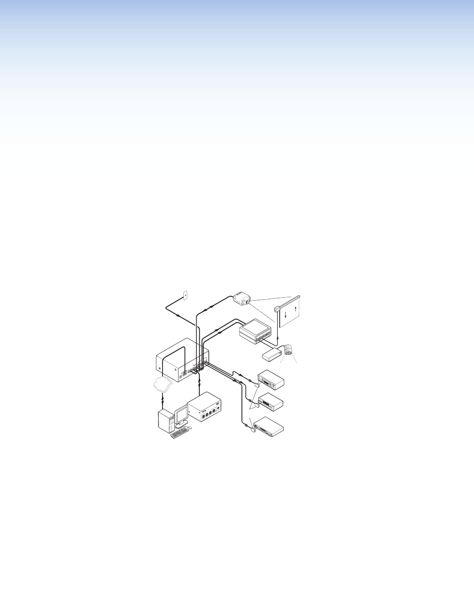
Connecting the Hardware
To connect the IPL T SFI244 interface, connect the input and output devices to the unit
using figure 8 as a guide. Before connecting the IPL T SFI244 to a local area network
(LAN) you must initially connect a PC directly to the IPL T SFI244 and change the default IP
address to an address specified by your network administrator (for a LAN connection).
Extron
IPL T RLY4
Relay Box
Lighting System
CO
M1
TX
RX
TX
RX
CO
M2
LA
N
00-05-A6-xx-xx-xx
PO
W
ER
12V
.5A
M
AX
FL
EX
I/O
2
1
3
4
1
IR
2
3
4
G
S
G
S
G
S
G
S
Screen
Control
Extron
IPL T SFI244
Ethernet Control
Interface
RS-232
RS-232
DVD 1
VCR/
DVD 2
Extron
IR Emitters
Projector
Ethernet
Remote User
Control &
Administrator
Monitoring
TCP/IP
Network
Motion Detector
Extron
MLS 103 SV
S-video & Audio
Switcher
DSS Receiver
NO
C
N
C
NO
C
N
C
NO
C
N
C
NO
C
N
C
RE
LA
Y 1
RE
LA
Y 2
REL
AY
3
RE
LA
Y 4
MLS 100 Se
ries
Med
iaL
ink
Sw
itc
her
AUX/MIX
LEVEL
INPUT SELECT
1
2
3
4
Figure 8.
Example Application
Ethernet Connection
This type of connection is used on an ongoing basis to connect the IPL T SFI244 unit and
to control switching and display devices through the unit.
1.
Plug one end of a CAT 5, straight-through Ethernet cable into the rear panel Ethernet
connector on the IPL T SFI244. See
2.
Plug the other end of the Ethernet cable into a network switch, hub, or router
connected to an Ethernet LAN or to the Internet.
3.
Launch your Web browser on your PC and type the Web address that you set up
on the IPL T SFI244 (see
IPLT T SFI244 Interface Configuration
) in the browser’s
Address field. The initial IPL T SFI244 default Web page is displayed.
IPL T SFI244 • Connection and Configuration
11