Identification, Operation, Front panel indicators – Extron Electronics IPL T SFI244 User Manual
Page 14
Identification
f
MAC address — The unique user hardware ID number (MAC address) of the unit (for
example, 00-05-A6-00-00-01).
Operation
Connect power cords and turn on the display output devices (projectors, monitors, VCRs),
control devices (switchers, scalers, network equipment).
Check indicator LEDs on the PC or laptop, on the unit and on the network hub or router,
and so on, to ensure that all devices are plugged in and communicating. The
IPL T SFI244 is now ready to be configured (see
If connection or communication problems occur, see
troubleshooting tips do not help, check with your local network administrator, or call the
Extron S
3
Sales & Technical Support Hotline.
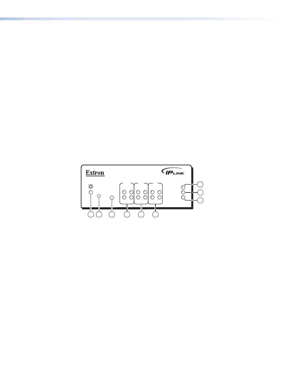
Front Panel Indicators
The front panel of the IPL T SFI244 has several indicator LEDs that show the current status
of communications to and from the unit. A Reset button (
b
) is also available from the
front panel, in a small recess next to the Power LED.
IPL T SFI244
1
R
100
COM
TX
LINK
ACT
2
RX
1
3
2
4
1
3
2
4
I/O
IR
®
4
5
6
8
7
3
2
1
9
Figure 7.
IPL T SFI244 Front Panel
a
Power LED — A green LED lights to indicate that the unit is receiving power.
b
Reset button (recessed) — See
for details on this multi-function
Reset button.
c
IR learning receiver — This smaller infrared receiver “learns” commands from other
devices’ IR remote controls. Refer to the IR Learner Software help file for IR Learning
procedures.
d
COM ports — A green LED indicates that data is being transmitted or received (TX or
RX).
e
I/O ports — A green LED indicates that the corresponding I/O port (1-4) is active.
f
IR ports — A green LED lights to indicate that the corresponding IR port (1-4) is
transmitting data.
g
100 LED — A green LED lights to indicate that the connection speed is 100 Mbps. If
IPL T SFI244 • Installation and Operation
8