Input connector, Remote configuration and control connectors, Input connector remote configuration and control – Extron Electronics AVT 200HD User Guide User Manual
Page 13: Connectors
AVT 200HD Tuner • Installation
7
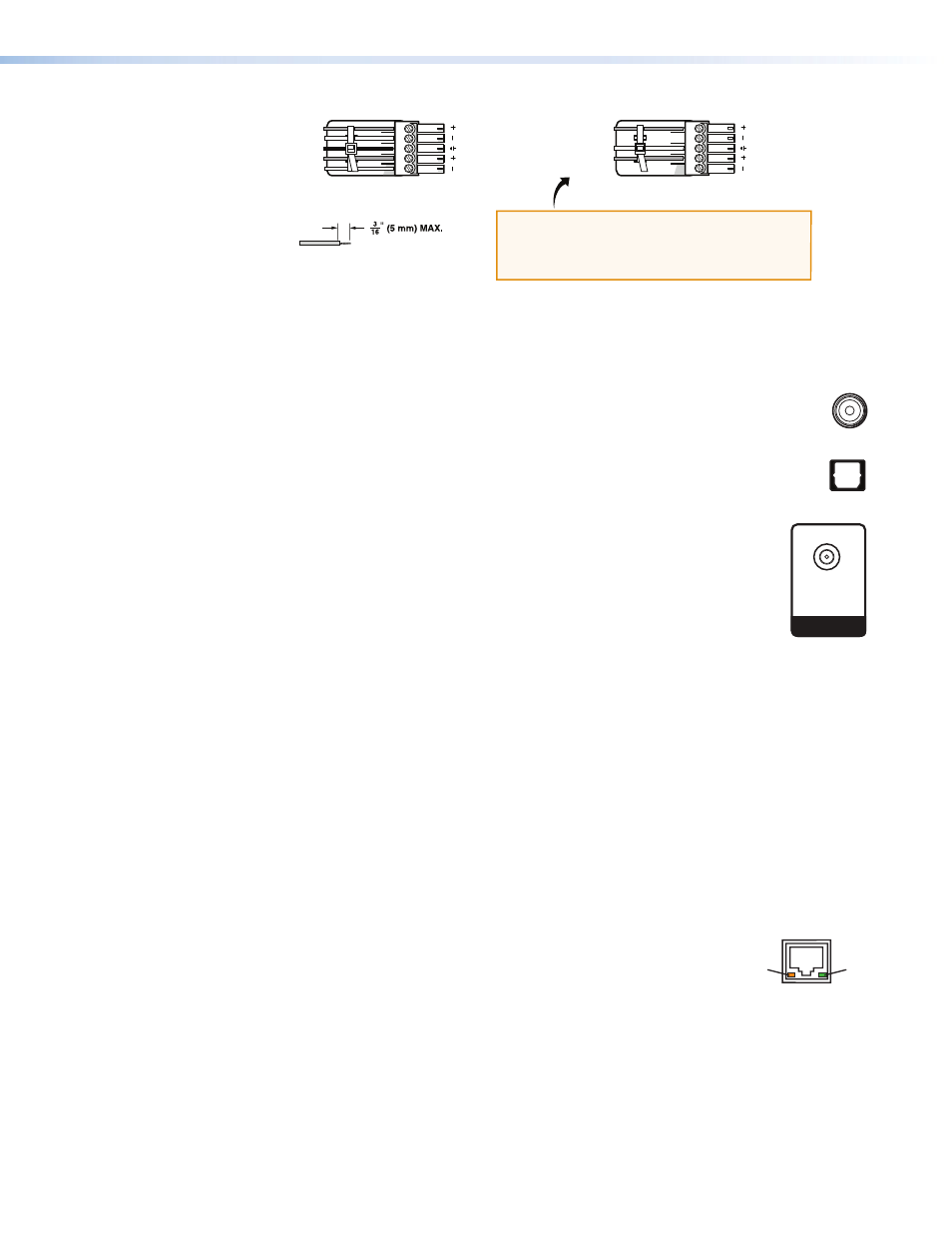
Balanced Audio Output
Unbalanced Audio Output
Tip
Ring
Tip
Ring
LR
Sleeve(s)
Do not tin the wires!
Tip
NO Ground Here
Sleeve(s)
NO Ground Here
Tip
LR
CAUTION:
For unbalanced audio, connect the sleeves to the
ground contact.
DO NOT
connect the sleeves to negative (–) contacts.
Figure 5.
Wiring the Captive Screw Audio Connector
Digital audio output connectors
Both digital ports support AC-3 and PCM digital audio.
h
Coax port — Connect a digital audio output device to this coaxial RCA jack for
S/PDIF signal transmission.
i
Optical port — Connect a digital audio output device to this TOSLINK
™
fiber
optic connector for S/PDIF signal transmission.
Input Connector
j
Air/Cable RF In connector — Plug an antenna or a CATV cable into this
F-type connector for over-the-air or cable radio frequency (RF) input.
Remote Configuration and Control Connectors
The following connectors are available for remote configuration and control of the
AVT 200HD from a computer or other control system or via IR remote control.
k
RS-232/IR connector — Connect a host device, such as a computer, touch panel
control system, or RS-232 capable PDA to this 5-pole captive screw connector for
entering SIS commands and using the Windows-based control software (see “
” later in this section, for information on connecting to this port).
To extend IR control, you can also connect an optional IR Link to this port (see “
,” later in this section).
l
LAN port — If desired, connect the AVT 200HD to a computer or to an Ethernet
LAN via this RJ-45 connector. Through this port, you can control the tuner using SIS
commands, the
AVT 200HD Configuration & Control Program
that are pre-loaded on the AVT (see “
,” on the next page).
The two LEDs on this connector indicate the status of the Ethernet
connection. The amber activity LED indicates that the RJ-45
connector is transmitting or receiving data. This LED flickers as the
tuner communicates. The green link LED indicates that the AVT is
properly connected to an Ethernet LAN. This LED lights steadily.
m
Reset button — This recessed button initiates four reset modes on the AVT 200HD. To
select a reset level, use a pointed object such as a small Phillips screwdriver to press and
hold the button while the AVT is running or while it is powering up (see “
” in the “Operation” section).
n
Reset LED — When you are selecting a reset mode, this LED blinks the appropriate
number of times to indicate the level of reset or that the reset is complete.
LAN
Activity
Link
COAX
OPTICAL
AIR/CABLE
RF IN