Rear panel features, Video output connectors, On the – Extron Electronics AVT 200HD User Guide User Manual
Page 11: Rear panel diagram, Rear panel, Diagram, Rear, Panel diagram, Avt 200hd tuner • installation 5
AVT 200HD Tuner • Installation
5
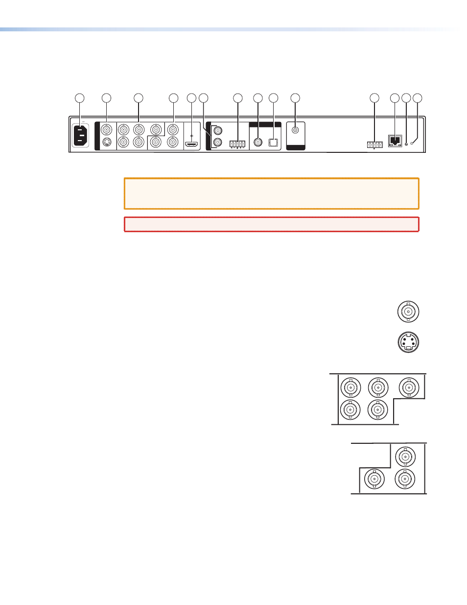
Rear Panel Features
All of the AVT 200HD connectors are on the rear panel. The following figure shows the AVT
rear panel features.
VID
R
H
V
B-Y
Y
G
B
R-Y
COAX
HDMI
OPTICAL
AIR/CABLE
50/60 Hz
LAN
RESET
YC
100-240V 0.8A
O
U
T
P
U
T
A
U
D
I
O
O
U
T
DIGITAL AUDIO
RF IN
L
L
R
R
Tx
IR +12V
RS-232/IR
Rx
14
1
2
3
4
7
8
9
10
11
12 13
6
5
Figure 2.
AVT 200 Rear Panel
CAUTION: Use electrostatic discharge precautions (be electrically grounded) when
making connections. Electrostatic discharge (ESD) can damage equipment,
although you may not feel, see, or hear it.
WARNING: Remove power from the system before making any connections.
a
AC power connector — Plug a standard IEC power cord into this connector to connect
the tuner to a 100 VAC to 240 VAC, 50 or 60 Hz power source.
Video Output Connectors
b
Composite and S-video stacked video output connectors —
•
VID (top): Connect a composite video output device to this female BNC
connector.
•
YC (bottom): Connect an S-video output device to this female 4-pin mini
DIN connector.
These connectors output simultaneously when the 480i output rate is selected.
c
RGBHV output connectors — Connect an RGBHV
output device to these five female BNC connectors. This
output supports 480i, 480p, 720p, and 1080i resolutions.
d
Component video output connectors — Connect an
HD YUV output device to these three female BNC connectors.
These outputs support 480i, 480p, 720p, and 1080i resolutions.
R
H
V
G
B
B-Y
Y
R-Y
VID
YC