GE Industrial Solutions 6KCV300WPD User Manual
Page 53
9.3. I
Monitor Configuration Dialog
This dialog is used for setting the display configuration of the monitor window:
the Y range can be set automatically or manually by entering the minimum and maximum values,
X and Y axis can be displayed or hidden,
Cross lines at the actual position of the mouse pointer together with a display of the x and y values can be
displayed,
the x axis range can be set by a scrollbar.
OK will apply these changes while Cancel leaves everything unchanged.
9.3.2
Changing the fist of Probes
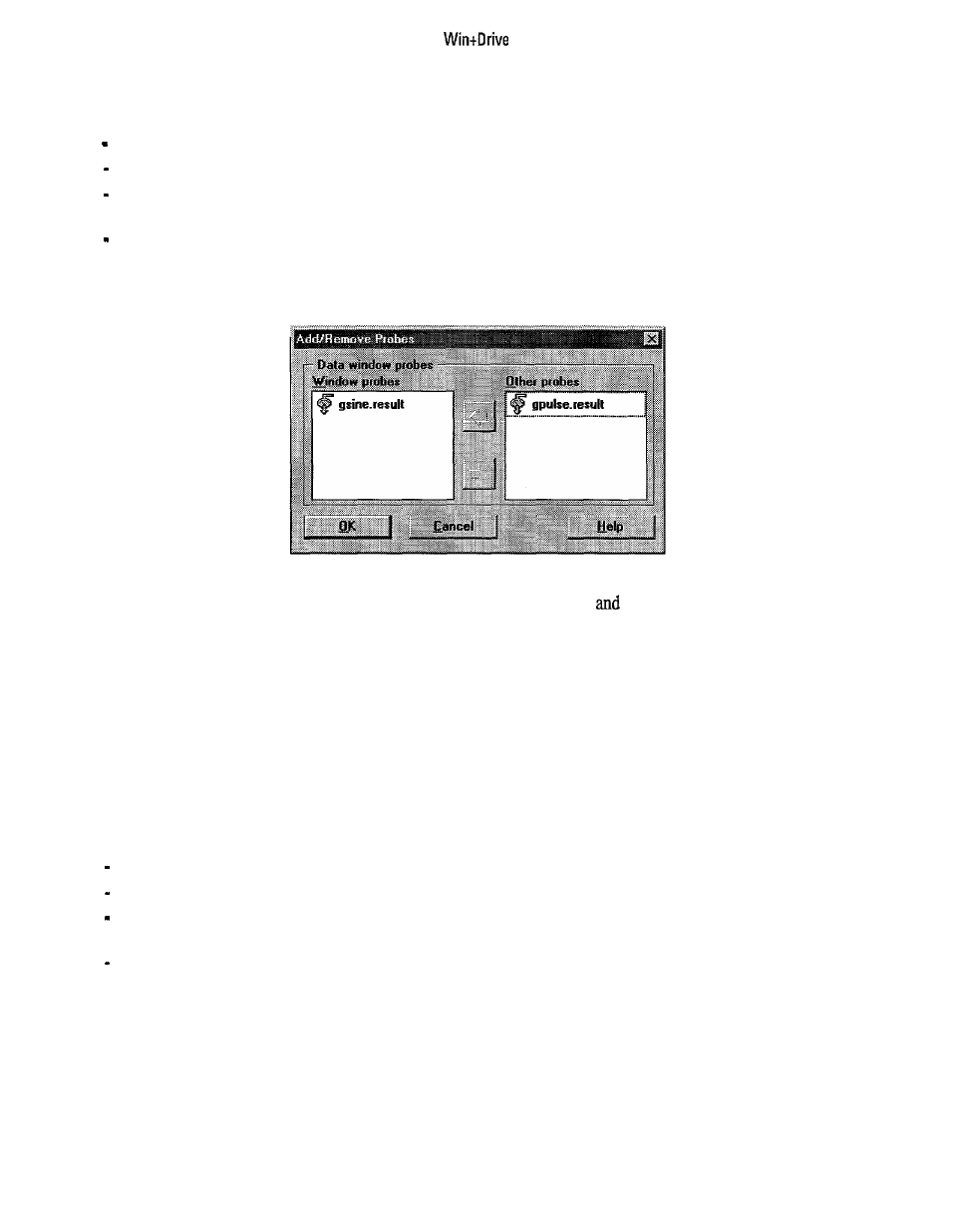
Figure9.3.2.1: Setting the List of Probes
The list of probes dialog includes two list boxes. The left one includes the probes that are displayed in the
monitor window while the right one includes all others. Selecting an item
moving it from one list to the
other using the arrow buttons will include or exclude it from display in this window. OK ends this setup while
Cancel leaves it unchanged.
9.3.3
Zoom within the Monitor Window
To enlarge the view in a monitor window a rectangle can be drawn with the left mouse button pressed down.
This area will be zoomed and displayed in the total window.
Pressing the right mouse button while in a zoomed view will go back to the original size.
9.4
Configuration of the Trace Window
The trace window is modified by items from a context sensitive menu that is opened by pressing the right
mouse button while the trace window has the focus. The following menu items are available:
Show Grid and Hide Grid control the display of horizontal lines between each line.
Align Left and Centering control the display of the values.
List of Probes will change the probes that are displayed in this window (see description of the menu item
of the monitor window above)
Save as Text File will write the contents of the Trace Window to a text file. The filename is entered by
the standard windows file dialog.
4 3