GE Industrial Solutions 6KCV300WPD User Manual
Page 27
rive
C r e a t i n g
S c h e m a t i c s
Building programs using Win+Drive is very similar to creating electrical circuit descriptions. It consists
mainly of two actions:
selecting and placing blocks of code onto the schematic
and connecting these blocks.
5 . 1
Placing Software Blocks
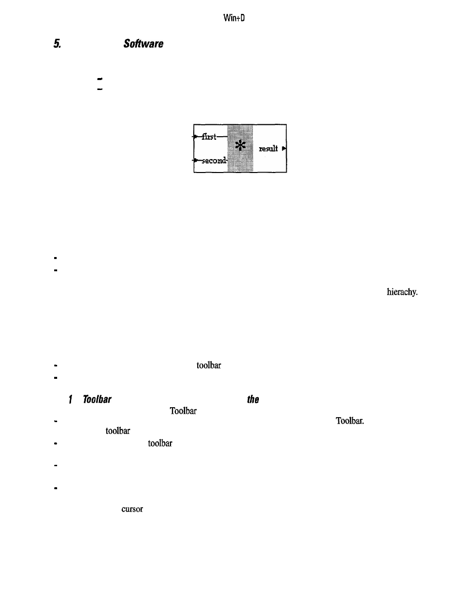
Figure 5.1: Block
A block is always the representation of a specific function that is performed by a piece of code. This software
function evaluates input values which are represented by input ports and calculates output values which are
represented by output ports. If the input port of a block is connected to the output port of another then this
block will read the results of this preceding block.
There are two different types of blocks:
basic blocks
compound blocks.
Basic blocks are the atomic building parts and always represent software code. Compound blocks are repre-
sentations of schematics and are used for dividing the total project into several schematics within a
Compound blocks will be described in detail in Chapter 7.
Basic blocks are organized in groups. Since there can be a large number of different basic blocks its easier to
select them if there is this kind of organization and ordering. Groups are normally organized in a way that
basic blocks with similar functions are grouped together (for example arithmetic blocks, logical blocks,
function generators).
For placing blocks onto the schematic two different methods are implemented:
placing by drag&drop from the block
and selecting from the insert menu.
5.1.
Placing Blocks by Drag&Drop from
Block
To place a block from the Block
perform the following actions:
first select the appropriate group by clicking an icon of the left side of the Block
Now the right
half of this
will display the members of this group
select a block from the
by moving the mouse onto its icon and pressing the left mouse button. The
mouse cursor will change to a symbol representing a block
hold down the left mouse button and
move
the mouse to the place within the schematic the block should
be placed (Drag action)
At this point release the mouse button. The block will be placed at this point (Drop action).
If the mouse is positioned on a point where the block cannot be placed (outside the client area of a schematics
window) the mouse
changes to a symbol showing that no drop action is possible.
1 7