GE Industrial Solutions 6KCV300WPD User Manual
Page 18
GEL100340
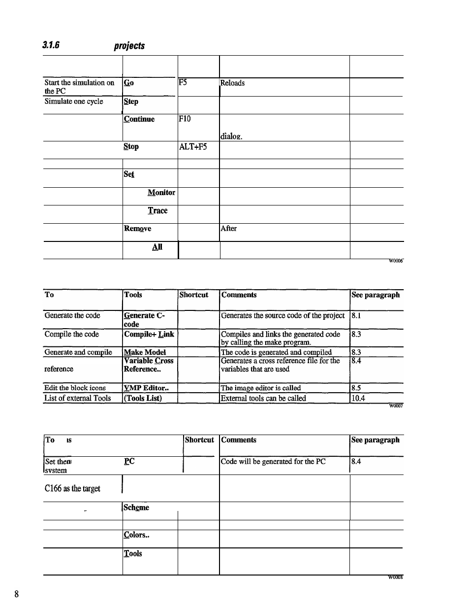
D e b u g g i n g
To
Debug
Simulate several cycles
Stop the simulation
I
Unload the model
Unload DLL
Set probe on signal.
Probe
Create a monitor
Create a trace
Remove a probe
Remove all probes
create
Create
Probe
Remove
Probes
Shortcut
Comments
See paragraph
F8
the model into memory and
initializes it.
9.5
The model is simulated once on the PC
9.5
The model is simulated several times.
9.5
The number of cycles is determined by a
The model is unloaded and the data is
9.5
removed from the monitors
The model is removed from memory.
9.5
A probe is set on the selected signal
9.1
(connection line)
After selecting this menu item a signal is 9.1.1
selected which is monitored.
After selecting this menu item a signal is 9.1.1
selected to trace a signal.
selecting this menu item a probe is 9.2
selected which will be removed.
All probes within the project are
removed.
9.2
3 . 1 . 7 T o o l s
Generate a cross
3 . 1 . 8 O p t i o n s
Set the PC as the target
Simulation
Set the microcontroller
Target
Execution
I
system
I
I
Set the settings of the
schematic
Set general settings
Set the colors
Settings..
settings..
Setting the external tools
Code will be generated for the target
8.4
system
‘A dialog is opened for setting options of 10.1
the schemes
A dialog is opened for general settings.
10.2
A dialog is opened for setting the colors
10.3
within the schematics.
A dialog is opened that where external
10.4
tools that extend the tools menu are
defined