Ats types, Standard transition, Delayed transition – GE Industrial Solutions MX350 Instruction manual User Manual
Page 78: Ats types - 4
5–4
MX350 AUTOMATIC TRANSFER CONTROL SYSTEM – INSTRUCTION MANUAL
CONFIGURATION SETPOINTS
CHAPTER 5: SETPOINTS
ATS types
The following is a brief description of how each type of switch works in a typical setup. i.e.
S1 is utility power and S2 is engine generator power:
Standard transition
SOURCE 1 POWER FAILURE:
When the Source 1 voltage or frequency has fallen below the values as set up in the
Setpoints > Operations > S1 Settings screen, the controller initiates the P timer (engine
start delay timer). Upon the completion of the P time delay, an Engine Start signal is sent to
Source 2, typically an engine generator set. When frequency and voltage of S2 reach the
values as set up in the Setpoints > Operations > S2 Settings screen, the W timer (time
delay to S2) begins timing. The W time delay ensures that source 2 is stable before actually
transferring to this source. If desired, the operator can bypass this timer from the Status
screen, or through a remote signal. After the W time delay, the MX350 energizes SCR-E to
move the switch to the S2 position, transferring the load to Source 2.
SOURCE 1 POWER RESTORATION:
When Source 1 is recovering and reaches the presets as set up in the Setpoints >
Operations > S1 Settings screen, the controller initiates a re-transfer to Source 1. In order
to ensure that the utility voltage and frequency are stable before transferring back to
Source 1, the delay to Source 1 (T) timer begins to time for a period of time as set up by the
user, typically set to 30 minutes. If the user wishes to re-transfer before the T timer has
expired, he or she can highlight the timing message on the Status screen and bypass the
timer by depressing the Bypass soft key. When the T timer has timed out or the Bypass key
has been depressed, the ATS will transfer the load back to Source 1.
The controller maintains the engine start signal for the time period specified as the U timer
(delay to stop engine) in order to ensure proper cooling of the engine before shutting it
down. If the operator desires to turn off the engine before the U timer has expired, he can
highlight the timing message on the Status screen and bypass the timer by depressing the
Bypass soft key. When the U timer has timed out or the Bypass key has been depressed,
the engine start signal will be removed, causing the engine to shut down.
Delayed transition
SOURCE 1 POWER FAILURE:
When the Source 1 voltage or frequency has fallen below the values as set up in the
Setpoints > Operations > S1 Settings screen, the controller initiates the P timer (engine
start delay timer). Upon the completion of the P time delay, an Engine Start signal is sent to
Source 2, typically an engine generator set. When frequency and voltage of S2 reach the
values as set up in the Setpoints > Operations > S2 Settings screen, the W timer (time
delay to S2) begins timing. The W time delay ensures that source 2 is stable before actually
transferring to this source. If desired, the operator can bypass this timer from the Status
screen or through a remote signal. After the W time delay, the MX350 energizes SCR-NO to
move the switch to the open position, where the load is connected to neither source.
Once the switch is in the open position, the delay to Source 2 (DW) timer starts its timing
cycle. Upon completion of the DW timer, the energizes SCR-E in order to transfer the load
to source 2.
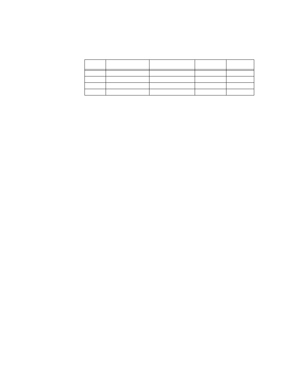
Name on Status/
Outputs Screen
Associated Function
Standard/Open
Transition
Delay/Closed
Transition
SCR-N
S1 Sol Relay
Connect load to S1
Yes
Yes
SCR-NO
S1 Delay Relay
Disconnect load from S1 N/A
Yes
SCR-E
S2 Sol Relay
Connect load to S2
Yes
Yes
SCR-EO
S2 Delay Relay
Disconnect load from S2 N/A
Yes