Cpu module, Rs485 connections, Cpu module - 9 – GE Industrial Solutions MX350 Instruction manual User Manual
Page 25: Chapter 2: installation electrical installation
CHAPTER 2: INSTALLATION
ELECTRICAL INSTALLATION
MX350 AUTOMATIC TRANSFER CONTROL SYSTEM – INSTRUCTION MANUAL
2–9
CPU module
The main CPU module and optional communications board is contained in slot B. The main
CPU module provides a Modbus RTU RS485 port. The optional communications board
provides an Ethernet port.
RS485 connections
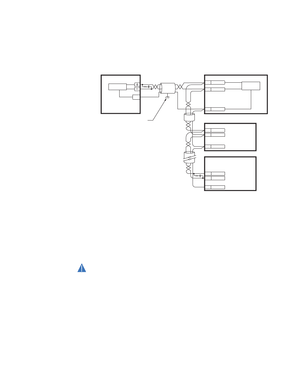
Figure 10: Typical RS485 connection
One two-wire RS485 port is provided. Up to 32 MX350 IEDs can be daisy-chained together
on a communication channel without exceeding the driver capability. For larger systems,
additional serial channels must be added. Commercially available repeaters can also be
used to add more than 32 relays on a single channel. Suitable cable should have a
characteristic impedance of 120 ohms (for example, Belden #9841) and total wire length
should not exceed 1200 meters (4000 ft.). Commercially available repeaters will allow for
transmission distances greater than 1200 meters.
Voltage differences between remote ends of the communication link are not uncommon.
For this reason, surge protection devices are internally installed across all RS485 terminals.
Internally, an isolated power supply with an optocoupled data interface is used to prevent
noise coupling.
CAUTION
CAUTION:
To ensure that all devices in a daisy-chain are at the same potential, it is imperative
that the common terminals of each RS485 port are tied together and grounded only
once, at the master or at the MX350. Failure to do so may result in intermittent or failed
communications.
The source computer/PLC/SCADA system should have similar transient protection devices
installed, either internally or externally. Ground the shield at one point only, as shown in the
figure above, to avoid ground loops.
Correct polarity is also essential. The MX350 IEDs must be wired with all the positive (+)
terminals connected together and all the negative (–) terminals connected together. Each
relay must be daisy-chained to the next one. Avoid star or stub connected configurations.
The last device at each end of the daisy-chain should be terminated with a 120 ohm
¼ watt resistor in series with a 1 nF capacitor across the positive and negative terminals.
Observing these guidelines will ensure a reliable communication system immune to
system transients.
SCADA, PLC, OR
PERSONAL COMPUTER
COM
OPTOCOUPLER
DATA
IED
SHIELD
889745A1.CDR
UP TO 32 IEDs,
MAXIMUM CABLE
LENGTH OF
1200 m (4000 ft.)
LAST
DEVICE
(*) TERMINATING IMPEDANCE AT EACH END
(typically 120 ohms and 1 nF)
TWISTED PAIR
ZT (*)
RS485 +
RS485 -
COMMON
RS485 +
RS485 -
COMMON
IED
RS485 +
IED
RS485 -
COMMON
GROUND THE SHIELD AT THE
SCADA/PLC/COMPUTER ONLY
OR THE UNIT ONLY
DATA
OPTOCOUPLER
B1
B2
B3
ZT (*)