GE Industrial Solutions MX350 Instruction manual User Manual
Page 40
3–10
MX350 AUTOMATIC TRANSFER CONTROL SYSTEM – INSTRUCTION MANUAL
GRAPHICAL CONTROL PANEL
CHAPTER 3: INTERFACING WITH THE MX350 AT CONTROLLER
Figure 12: setpoints home page
To streamline the setpoint entry process, the graphical control panel will not display
setpoints that are not relevant at the specific instance. For instance, if a process interlock
function is disabled, the six setpoints associated with that interlock function will not be
displayed. If all ten process interlock functions are disabled, the MX350 will display only 10
successive “Disabled” list items. If one of the interlock functions were then enabled, then
room is made on the display for the six setpoints which are now functional.
The setpoint pages are in a common format of up to twelve lines. Each line has a column
that displays the setpoint name and unit, and another column displaying the value
entered.
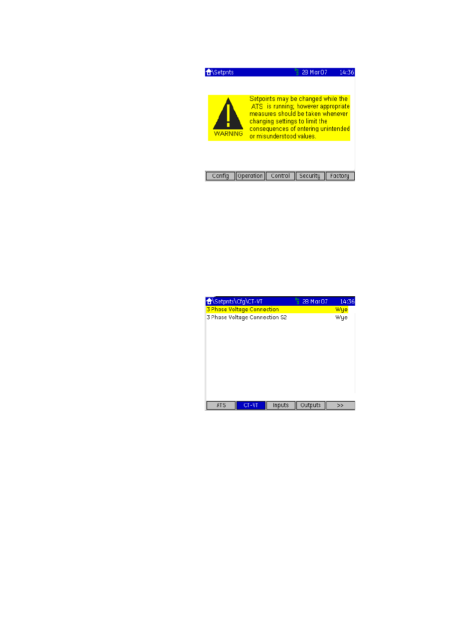
The Home > Setpoints > Config > CT-VT page is shown below.
Figure 13: Typical setpoints page
Diagnostics pages
The diagnostic pages are divided into five sections.
•
Events (event recorder data for up to 256 events)
•
Stats (statistical data on the last transfer event)
•
Phasors (metered phasor data)
•
About (product information)
Typical diagnostic pages for Events, Stats, Phasors, and Product Information are shown
below.