Input/output modules, Phase current inputs (io_a module), Input/output modules - 10 – GE Industrial Solutions MX350 Instruction manual User Manual
Page 26
2–10
MX350 AUTOMATIC TRANSFER CONTROL SYSTEM – INSTRUCTION MANUAL
ELECTRICAL INSTALLATION
CHAPTER 2: INSTALLATION
Input/Output modules
Phase current inputs
(IO_A module)
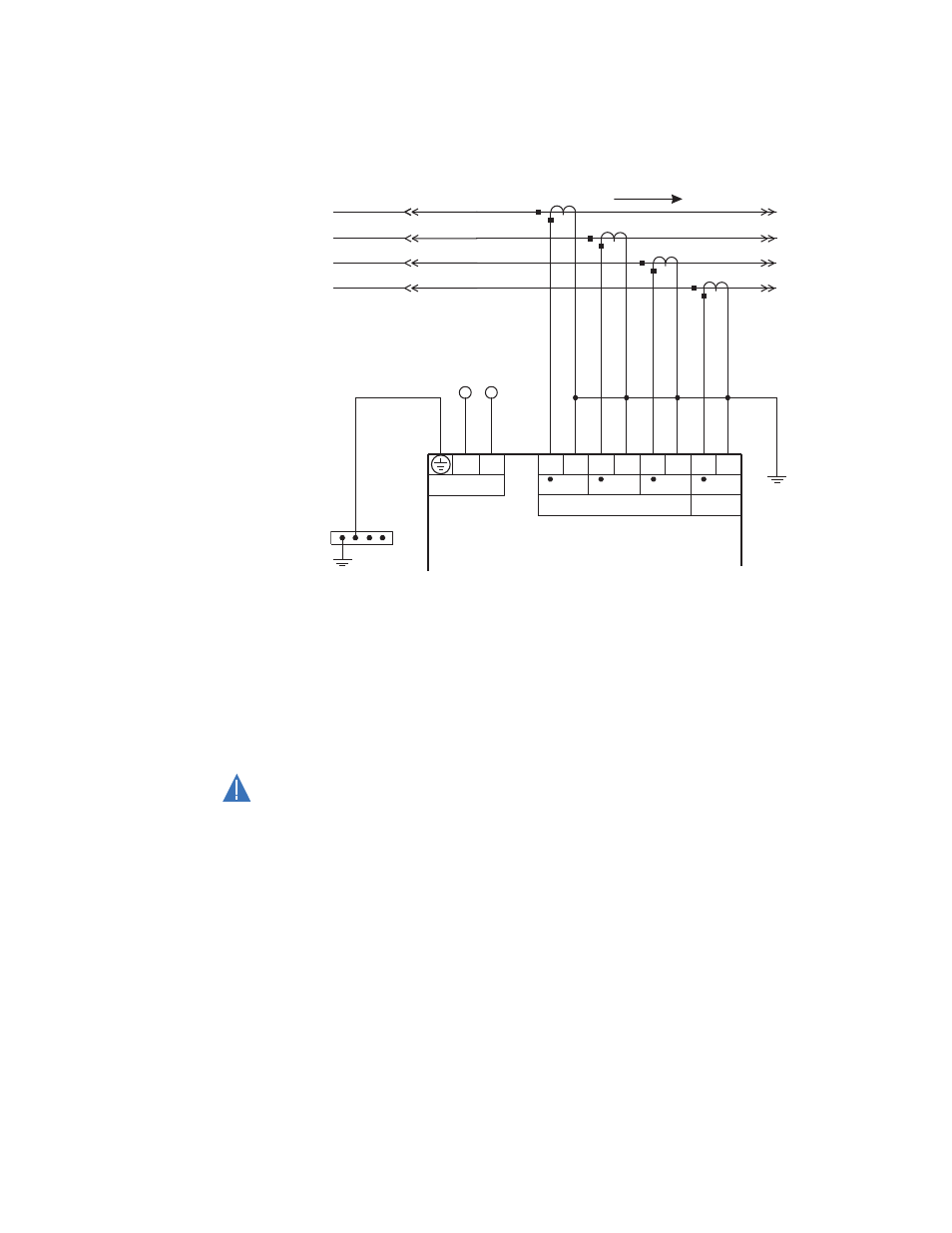
Figure 11: Typical phase current input connections
The MX350 has three channels for phase current inputs, plus an additional channel input
for ground/neutral current, each with an isolating transformer. The phase CTs should be
chosen so the nominal current is not less than 50% of the rated phase CT primary. Ideally,
the phase CT primary should be chosen such that the nominal current is 100% of the
phase CT primary or slightly less, never more. This will ensure maximum accuracy for the
current measurements. The maximum phase CT primary current is 4000 A.
The MX350 measures up to 1.5 times the phase current nominal rating. CTs with 1 A or 5 A
secondaries must be used if the FLA is greater than 5 A. The chosen CTs must be capable
of driving the MX350 phase CT burden.
CAUTION
CAUTION:
Polarity of the phase CTs is critical for negative-sequence unbalance calculation,
power measurement, and residual ground current detection (if used).
A
C
B
Power flow
–
+
E1
E2
E4
E3
Phase current inputs
Automatic Transfer Control System
To switchgear
ground bus
889744A1.CDR
E5
E6
E7
CT1
CT2
CT3
Control power
L
N
E8
G/F
N