Electrical installation, Electrical installation - 7 – GE Industrial Solutions MX350 Instruction manual User Manual
Page 23
CHAPTER 2: INSTALLATION
ELECTRICAL INSTALLATION
MX350 AUTOMATIC TRANSFER CONTROL SYSTEM – INSTRUCTION MANUAL
2–7
Electrical installation
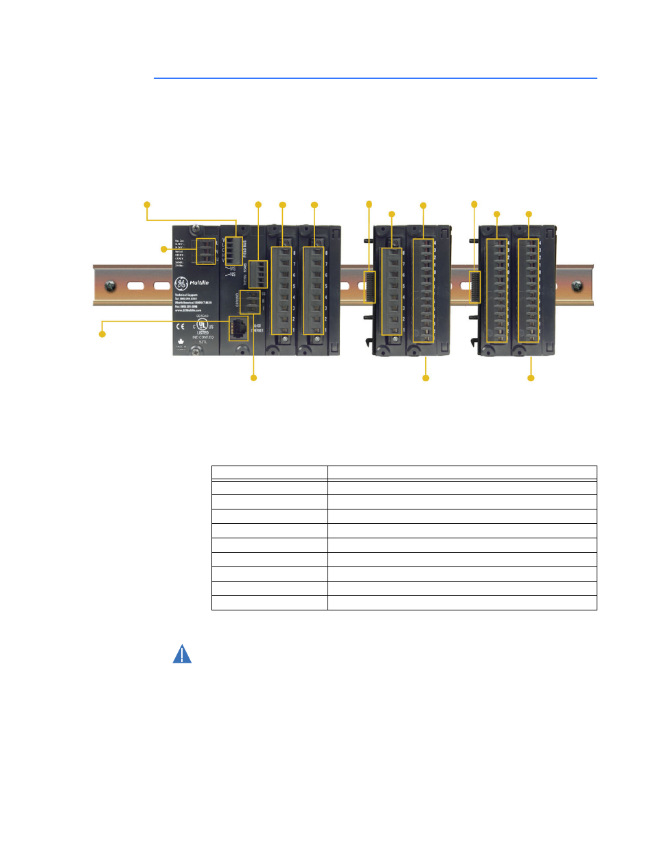
This section describes the electrical installation of the MX350 system. An overview of the
MX350 terminal connections is shown below.
Figure 8: MX350 terminal connection overview
The MX350 can contain up to ten modules. The first four modules (slots A through D) reside
in the base unit while all subsequent modules (slots E and J) reside in expansion units.
Each expansion unit can contain up to two modules. Slots A through G make up the basic
MX350. The next three modules (slots H through J) are optional I/O modules.
Table 2: Module slot position
The following figure shows a typical module arrangement for an expanded unit.
CAUTION
CAUTION:
Use gauge size appropriate for the voltage and current draw of the device.
The MX350 is not to be used in any way other than described in this manual.
Expansion module
Expansion module
to base unit with a
single connector
CT Input
Three-phase plus
ground/neutral
VT inputs
Optional TCP/IP
Ethernet
RS485 communications
Switched power supply
allows AC or DC control
voltage
889740A2.CDR
K Card
Expansion module
to base/expansion unit
with a single connector
L Card
L Card
Expansion module
Reserved
Reserved
Slot
Module types
A
Power supply module
B
CPU module with communications
C
IO_B module
D
IO_B module
E
IO_A module (optional)
F
IO_K module
G
IO_L module
H
IO_L module (optional)
I
IO_L module (optional)