GE Industrial Solutions MX350 Instruction manual User Manual
Page 39
CHAPTER 3: INTERFACING WITH THE MX350 AT CONTROLLER
GRAPHICAL CONTROL PANEL
MX350 AUTOMATIC TRANSFER CONTROL SYSTEM – INSTRUCTION MANUAL
3–9
•
Flex (displays the present state of the FlexLogic™ engine and number of lines used.)
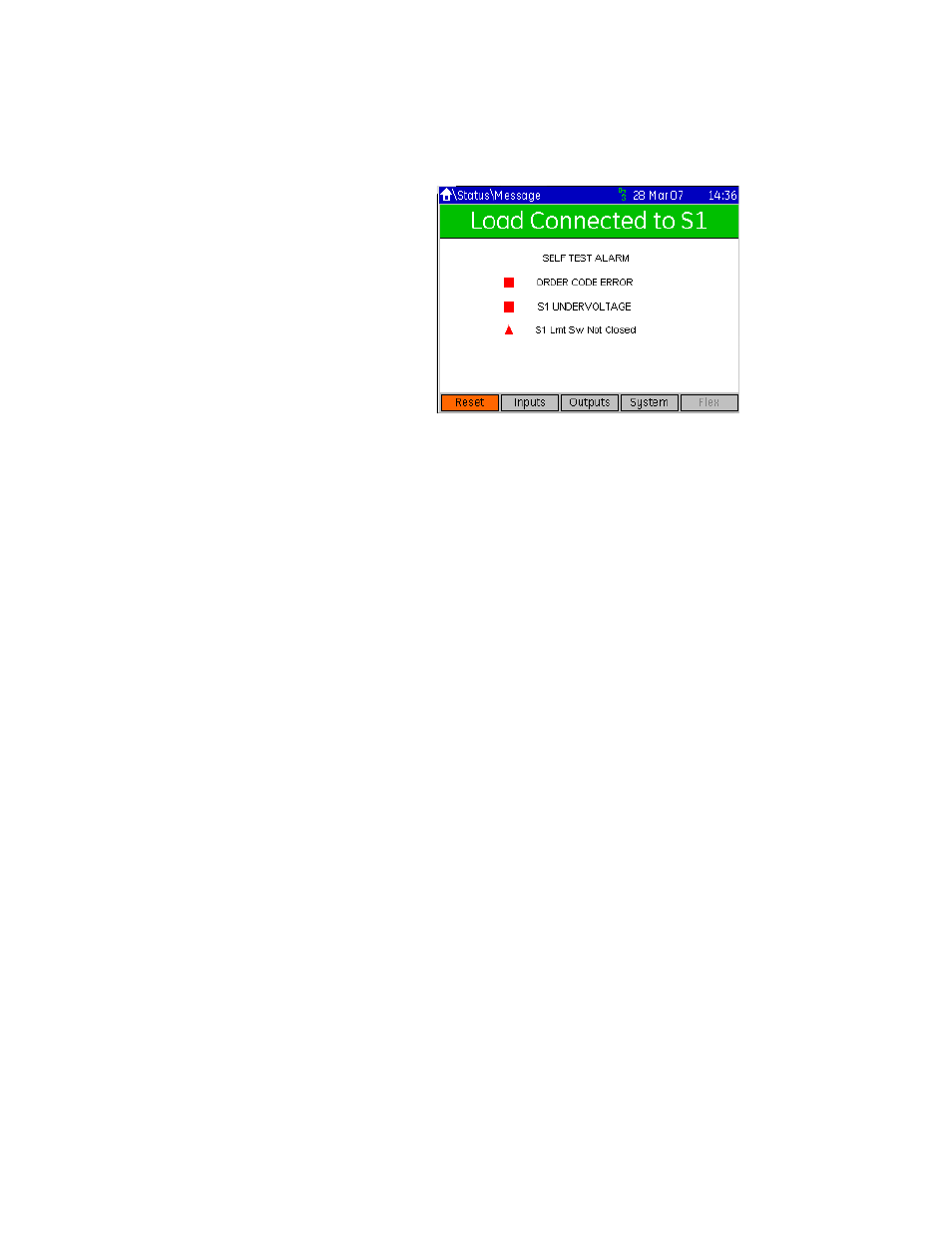
A typical display is shown below:
Figure 11: Typical status message page
Message types are classified by color and associated icon type, as follows::
•
Red Triangle = Alarm
•
Orange Square = Status
•
Black Text = Information Message
Message can have an associated countdown timer, if applicable.
When the controller is first powered up, the status page will display any parameters that
must be entered for proper operation of the associated ATS.
Inhibits
These include Transfer Inhibits like Q3 or Q7.
Faults / Alarms
These trigger depending on the respective protection setpoints. A typical example would
be “S1 Failure.”
Information Messages
Information can be one of two types:
–
information only
–
information with navigation (marked on the Status page with an Enter symbol on
the right)
By pressing the Enter key when an information message with navigation is highlighted, the
Grapical Control Panel will take the user directly to the respective page.
Setpoints pages
The Setpoints pages are divided into five sections.
•
Config (contains basic configuration setpoints)
•
Operation (contains range limits for both power sources and timer values for transfer
operations)
•
Control (contains basic control function setup, also accessible via the green CONTROL
key)
•
Security (contains the password security setpoints)
•
Factory (for access by GE only)
The Home > Setpoints page displays a warning message concerning unexpected
performance if setpoints are improperly changed. It is recommended that all relay outputs
capable of causing damage or harm be blocked before a setpoints change is made and it
is clear the relay is performing as intended with the new setpoints.