Type io_l module connections – GE Industrial Solutions MX350 Instruction manual User Manual
Page 29
CHAPTER 2: INSTALLATION
ELECTRICAL INSTALLATION
MX350 AUTOMATIC TRANSFER CONTROL SYSTEM – INSTRUCTION MANUAL
2–13
Type IO_L module
connections
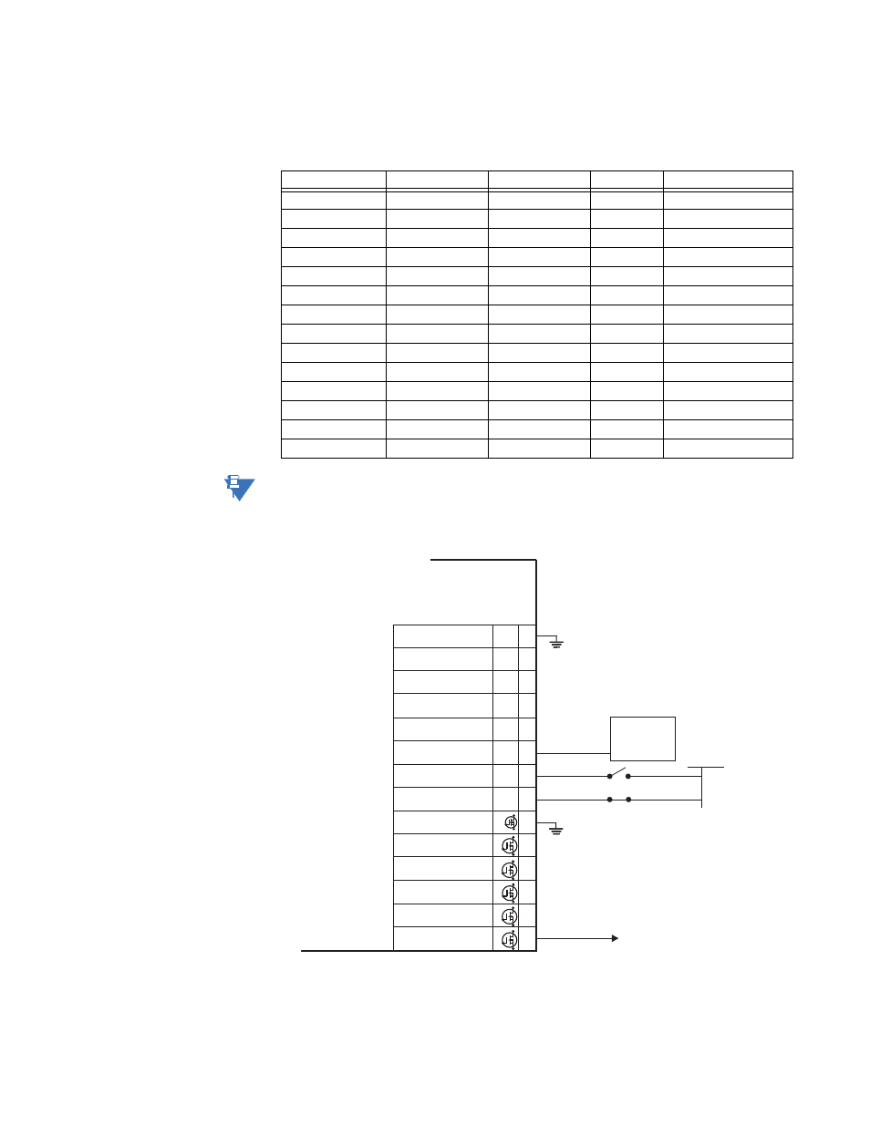
IO_L modules provide all user configurable I/O. Additionally, some of the I/O points on the
first L module in slot G are used for some factory configured I/O. The terminal
configuration is as follows:
NOTE
NOTE:
Terminals G7 and G8 are always used as DS and Q2, respectively. Depending on the type
of switch and the features ordered, Terminals G1 through G5 as well as G9 through G13
may not be available for customer configuration.
Figure 15: IO_L module - standard ATS
Terminal
Terminal
Terminal
Type
Function
G1
H1
J1
Output
Output 1
G2
H2
J2
Output
Output 2
G3
H3
J3
Output
Output 3
G4
H4
J4
Output
Output 4
G5
H5
J5
Output
Output 5
G6
H6
J6
Common
Common, Ouputs 1 to 5
G7
H7
J7
Input
Input 1
G8
H8
J8
Input
Input 2
G9
H9
J9
Input
Input 3
G10
H10
J10
Input
Input 4
G11
H11
J11
Input
Input 5
G12
H12
J12
Input
Input 6
G13
H13
J13
Input
Input 7
G14
H14
J14
Common
Common, Inputs 1 to 7
~1
~2
~4
~3
~5
~6
Auto Transfer Control
~8
~9
~11
~10
~12
~13
~7
~14
Inp
com
Inp 7
Inp 6
Inp 5
Inp 4
LOAD SHED FROM S2
TEST WITH LOAD
DISCONNECT SW
LOAD SHED FROM S2
SSR
COM
SSR3
SSR5
SSR4
SSR2
SSR1
NO
~1
~2
~4
~3
889742A1.CDR
~5
~6
Auto Transfer Control
~8
~9
~11
~10
~12
~13
~7
~14
Inp
com
In
SSR
SSR
NC
Inp 3
Inp 2
Inp 1
LOAD SHED
HARDWARE
FOR LOCAL
OPTION
TO BREAKER
24 V DC
0 VDC
0 VDC
USER DEFINED
USER DEFINED
USER DEFINED
USER DEFINED
USER DEFINED
USER DEFINED
USER DEFINED
USER DEFINED
USER DEFINED
USER DEFINED