Procedure for cvcc = 5volts – Rainbow Electronics AT89C5122 User Manual
Page 92
92
AT8xC5122/23
4202E–SCR–06/06
Procedure for CVcc = 5volts
The DC/DC pump mode must be selected (MODE = 0 in DCCKPS register). The
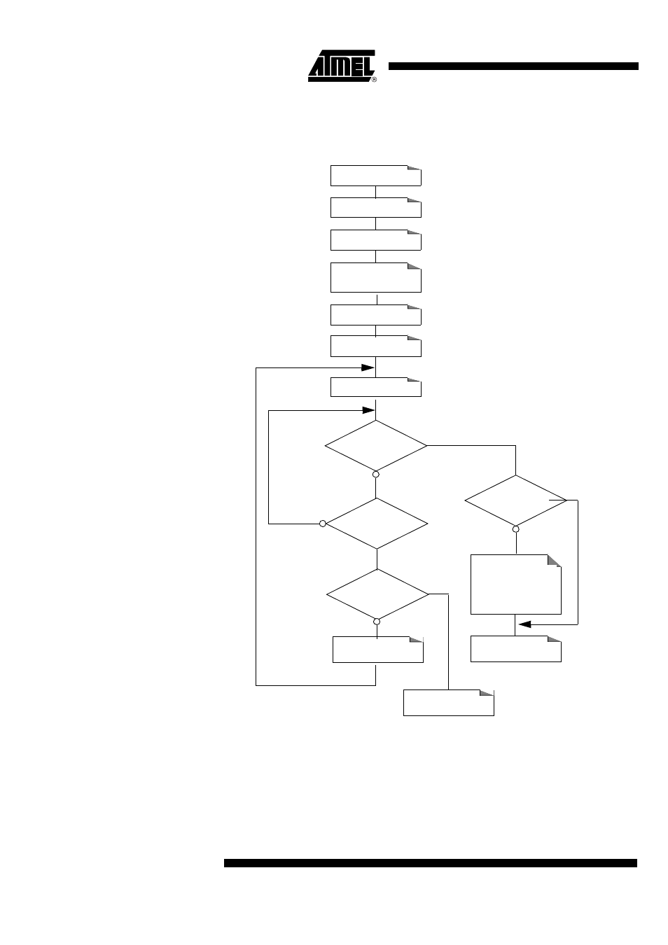
detailed procedure is described in flow chart of Figure 48.
Figure 48. Card Vcc = 5V Initialization Procedure
While VCC remains higher than 4.0V and startup current lower than 30 mA (depending
on the load type), the DC/DC converter should be ready without having to increment
BOOST[1:0] bits beyond [0:0] level. If VCC > 4.0V and startup current > 30 mA, it will be
necessary to increment the BOOST[1:0] bits until the DC/DC converter is ready.
Incrementation of BOOST[1:0] bits increases at the same time the current overflow level
in the same proportion as the startup current. So once the DC/DC converter is ready it is
SCCON CardVcc=1
VCARDOK=1
Set Timeout to 3 ms
Timeout
Expired
Increment
BOOST [1:0]
BOOST[1:0]
= max = 3?
DC/DC Initialization
Failure
DC/DC Initialization
Successful
Decrement
BOOST[1:0]
to adjust the
current overflow
Mode Pump
DCCKPS[7]=0
BOOST[1:0]=[0:0]
SCICR.7=Reset=0
SCICR.7=Reset=1
VCARD[1:0] = 11
BOOST[1:0]
= [0:0]