Baud rate selection (mode 2) – Rainbow Electronics AT89C5122 User Manual
Page 134
134
AT8xC5122/23
4202E–SCR–06/06
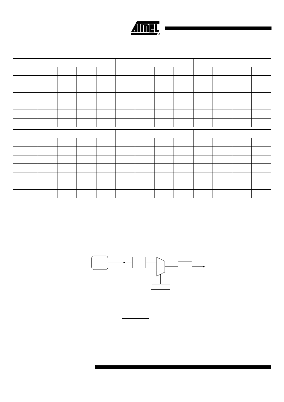
Baud Rate Selection (Mode 2)
In mode 2, the baud rate can only be programmed to two fixed values: 1/16 or 1/32 of
the peripheral clock frequency.
As shown in Figure 81 the selection is done using SMOD1 bit in PCON register.
Figure 82 gives the baud rate calculation formula depending on the selection.
Figure 81. Baud Rate Generator Selection (Mode 2)
Figure 82. Baud Rate Formula (Mode 2)
For mode 0 for UART, thanks to the bit M0SRC located in BDRCON register (Table 82)
Table 76. Internal Baud Rate Generator Value
Baud Rate
F
CK_IDLE
= 4 MHz
F
CK_IDLE
= 8 MHz
F
CK_IDLE
= 9.6 MHz
SPD
SMOD1
BRL
Error%
SPD
SMOD1
BRL
Error%
SPD
SMOD1
BRL
Error%
115200
1
1
254
8.51
1
1
252
8.51
1
1
251
4.17
57600
1
1
252
8.51
1
1
247
3.55
1
1
246
4.17
38400
1
1
249
6.99
1
1
243
0.16
1
1
240
2.34
19200
1
1
243
0.16
1
1
230
0.16
1
1
225
0.81
9600
1
1
230
0.16
1
1
204
0.16
1
1
194
0.81
4800
1
1
204
0.16
1
1
152
0.16
1
1
131
0.00
Baud Rate
F
CK_IDLE
= 12 MHz
F
CK_IDLE
= 16 MHz
F
CK_IDLE
= 24 MHz
SPD
SMOD1
BRL
Error%
SPD
SMOD1
BRL
Error%
SPD
SMOD1
BRL
Error%
115200
1
1
249
6.99
1
1
247
3.55
1
1
243
0.16
57600
1
1
243
0.16
1
1
239
2.12
1
1
230
0.16
38400
1
1
236
2.34
1
1
230
0.16
1
1
217
0.16
19200
1
1
217
0.16
1
1
204
0.16
1
1
178
0.16
9600
1
1
178
0.16
1
1
152
0.16
1
1
100
0.16
4800
1
1
100
0.16
1
1
48
0.16
1
1
N/A
N/A
0
1
SMOD1
PCON.7
CK_
SI
/ 2
³ 16
To Serial Port
Baud_Rate =
32
2
SMOD1
⋅
F
CK_SI