Interrupt generator – Rainbow Electronics AT89C5122 User Manual
Page 73
73
AT8xC5122/23
4202E–SCR–06/06
Removal of the smart card will automatically start the power off sequence as described
in Figure 39.
The SCIB deactivation sequence after a reset of the CPU or after a lost of power supply
is ISO7816-3 compliant. The switching order of the signals is the same as in Figure 39
but the delay between signals is analog and not clock dependant.
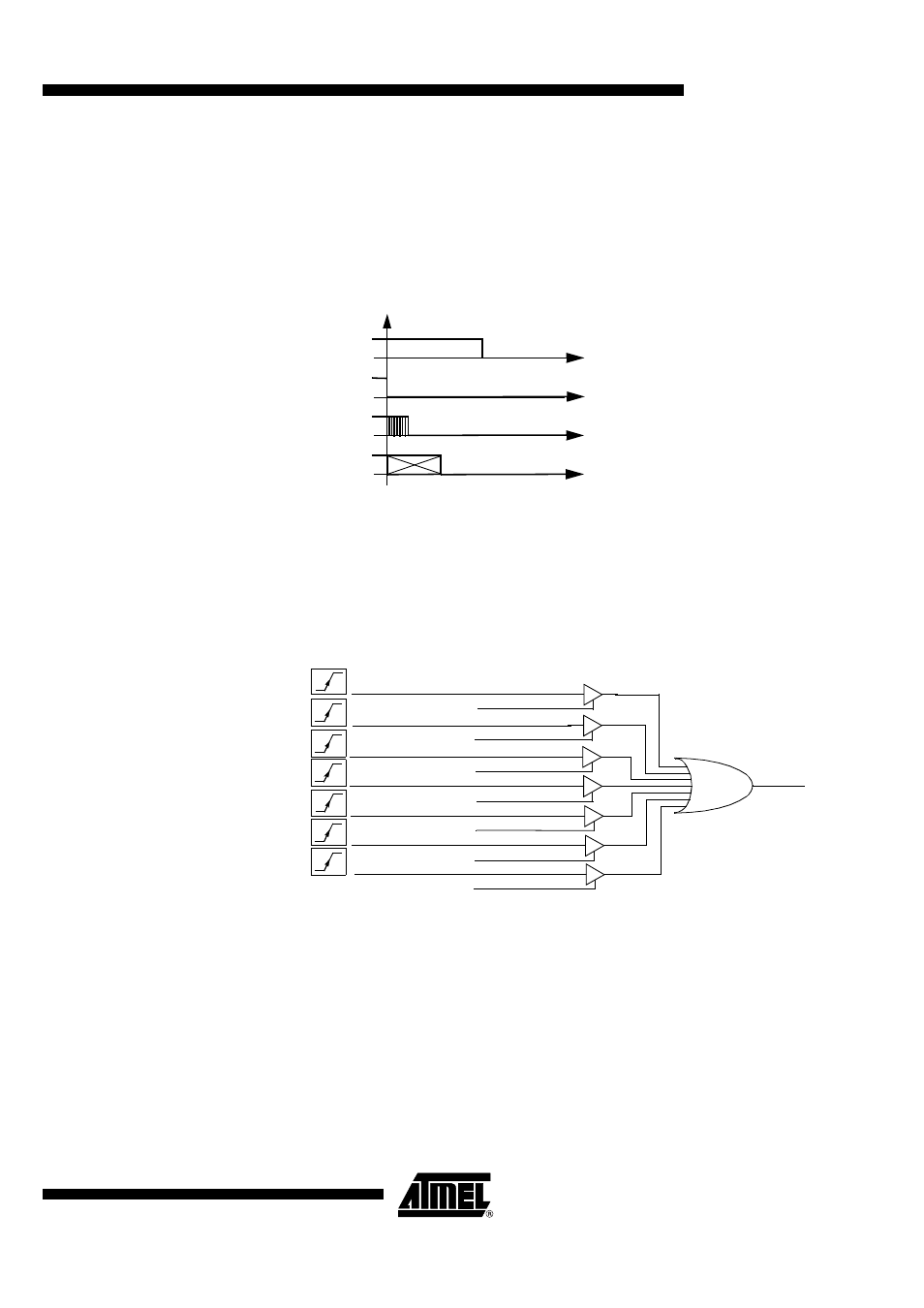
Figure 39. SCIB Deactivation Sequence after a Card Extraction
Interrupt Generator
There are several sources of interruption but the SCIB macro-cell issues only one inter-
rupt signal: SCIBIT.
Figure 40. SCIB Interrupt Sources
This signal is high level active. Each of the sources is able to activate the SCIB interrup-
ti on w hic h is cl ea red w he n the Sm a rt Card Interru pt reg ister i s rea d b y th e
microcontroller.
If during the read of the Smart Card Interrupt register another interrupt occurs, the acti-
vation of the corresponding bit in the Smart Card Interrupt register and the new SCIB
interruption is delayed until the interrupt register is read by the microcontroller.
Warning : Each bit of the SCIIR register is irrelevant while the corresponding interrup-
tion is disabled in SCIER register. When the interruption mode is not used, the bits of
the SCISR register must be used instead of the bits of the SCIIR register.
CVCC
CRST
CCLK
CIO
8 Clock Cycles
ESCTBI
ICARDER
ESCWTI
ESCRI
ESCPI
EVCARDER
Transmit buffer
copied to shift register
Output current
out of range
Output voltage
out of range
Timeout on WT
counter
Complete
transmission
Complete
reception
Parity error
detected
SCIB IT
ESCTI
SCTBI
ICARDERR
VCARDERR
SCWTI
SCTI
SCRI
SCPI