Smart card rst, cc4, cc8, dc parameters, Smart card cio, dc parameters, Card presence (p1.2) dc parameters – Rainbow Electronics AT89C5122 User Manual
Page 191
191
AT8xC5122/23
4202E–SCR–06/06
Note:
1. The voltage on RST should remain between -0.3V and
V
CC
+0.3V during dynamic operation.
Note:
1. The voltage on RST should remain between -0.3V and
V
CC
+0.3V during dynamic operation.
I
OL
Output Low Current
15
mA
V
OH
Output High Voltage
0.8 CV
CC
CV
CC
(1)
V
I
OH
= 20
μ
A
External 10K pull-up
resistor tied to CV
CC
I
OH
Output High Current
15
mA
Voltage Stability
-0.25
0.8 CV
CC
0.4
CV
CC
+ 0.25
V
Low level
High level
t
R
t
F
Rise and Fall delays
0.8
μ
s
C
IN
=30pF.
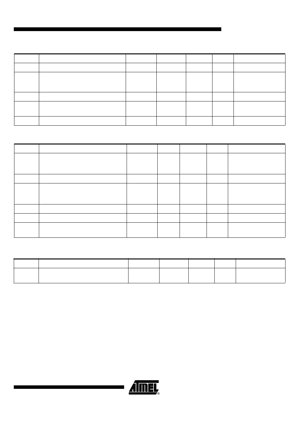
Smart Card RST, CC4, CC8, DC Parameters
Symbol
Parameter
Min
Typ
Max
Unit
Test Conditions
V
OL
Output Low Voltage
0
(1)
0.4
0.12 CV
CC
0.12 CV
CC
V
I
OL
= 50
μΑ (5
V until 2009)
I
OL
= 200
μΑ (5
V from 2009)
I
OL
= 200
μΑ
(3V & 1.8V)
I
OL
Output Low Current
15
mA
V
OH
Output High Voltage
CV
CC
-05
0.8 CV
CC
0.8 CV
CC
CV
CC
(1)
V
I
OH
= 50
μΑ
(+5V until 2009)
I
OH
= 150
μΑ
(+5V from 2009)
I
OH
= 150
μΑ
(+3V & 1.8V)
I
OH
Output High Current
15
mA
t
R
t
F
Rise and Fall delays
0.8
μ
s
C
IN
=30 pF
Voltage Stability
-0.25
CV
CC
-0.5
0.4 CV
CC
CV
CC
+ 0.25
Low level
High level
Smart Card CIO, DC Parameters
Symbol
Parameter
Min
Typ
Max
Unit
Test Conditions
Card Presence (P1.2) DC Parameters
Symbol
Parameter
Min
Typ
Max
Unit
Test Conditions
I
OL1
CPRES weak pull-up output current
3
10
25
μ
A
P1.2=1, short to VSS
Pull-up enabled