Block diagram, Definitions, Terminal and icc – Rainbow Electronics AT89C5122 User Manual
Page 65: Activation: cold reset, Activation: warm reset, De-activation
65
AT8xC5122/23
4202E–SCR–06/06
Block Diagram
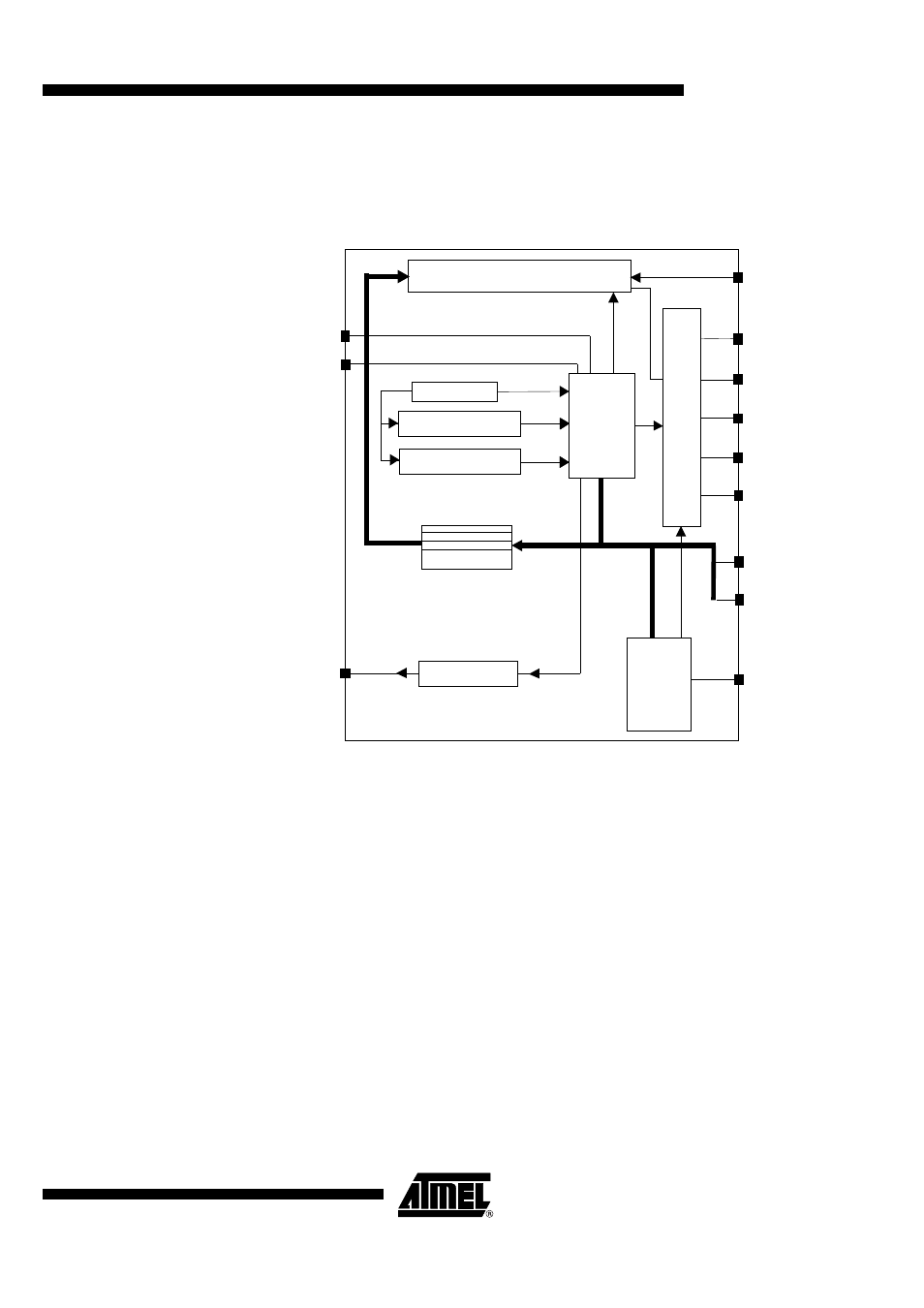
The Smart Card Interface Block diagram is shown Figure 30:
Figure 30. SCIB Block Diagram
Definitions
This paragraph introduces some of the terms used in ISO 7816-3 and EMV recommen-
dations. Please refer to the full recommendations for a complete list of terms.
Terminal and ICC
Terminal is the reader, ICC is the Integrated Circuit Card
ETU
Elementary Timing Unit (Bit time)
T=0
Character oriented half duplex protocol T=0
T=1
Block oriented half duplex protocol T=1
Activation: Cold Reset
Reset initiated by the Terminal with Vcc power-up. The card will answer with ATR (see
below)
Activation: Warm Reset
Reset initiated by the Terminal with Vcc already powered-up, and after a prior ATR or
Warm Reset
De-Activation
Deactivation by the Terminal as a result of : unresponsive ICC, or ICC removal.
Barrel shifter
Scart
fsm
Interrupt generator
Power on
Power off
fsm
I/O
mux
IO (in)
IO (out)
CLK
RST
C4 (out)
Clk_iso
C8 (out)
C4 (in)
C8 (in)
Waiting time counter
Guard time counter
VCARD
INT
Clk_cpu
Etu counter
SCI Registers