Registers – Rainbow Electronics AT89C5122 User Manual
Page 135
135
AT8xC5122/23
4202E–SCR–06/06
Registers
Reset Value = 0000 0000b (Bit addressable)
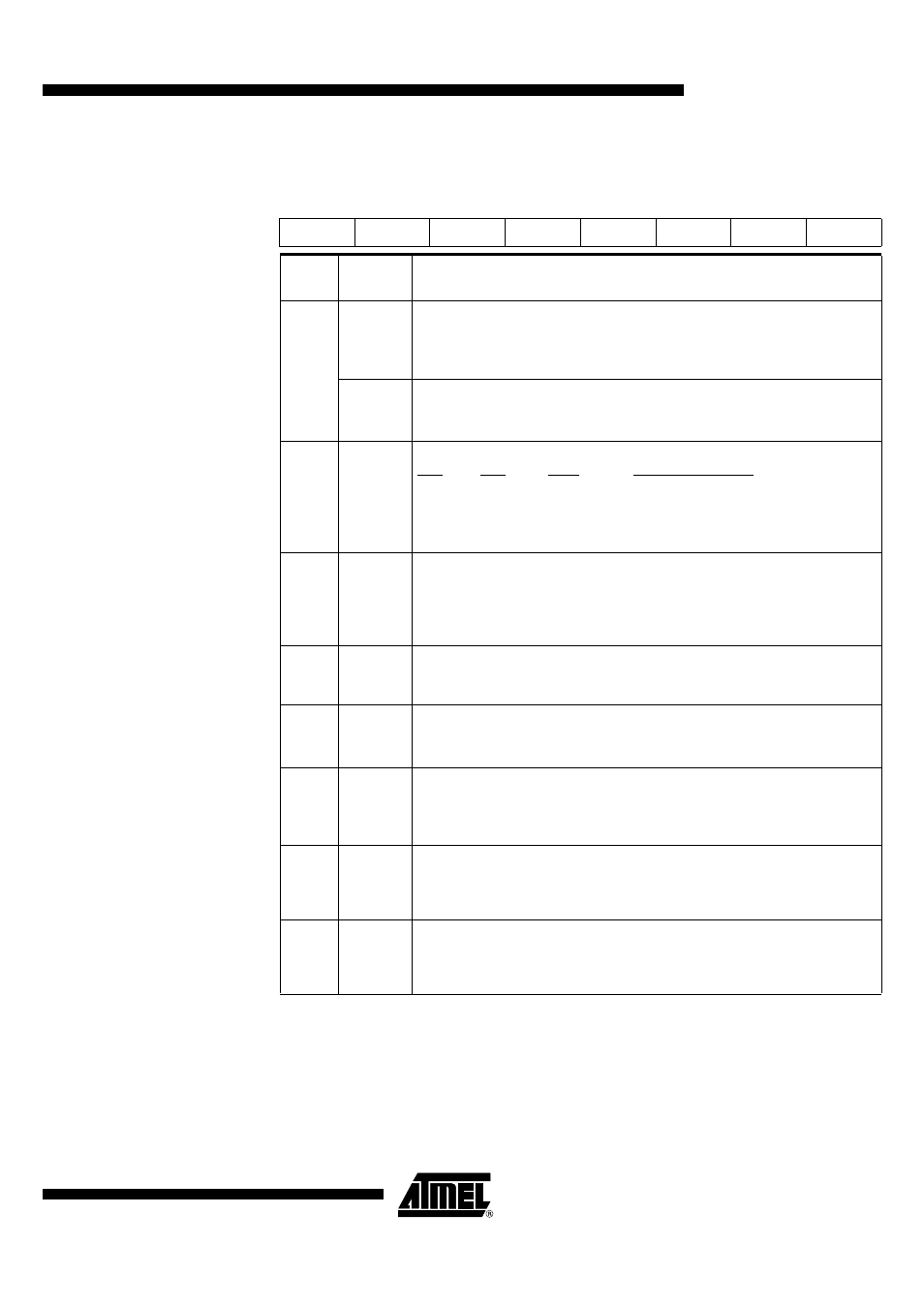
Table 77. Serial Control Register - SCON (98h)
7
6
5
4
3
2
1
0
FE/SM0
SM1
SM2
REN
TB8
RB8
TI
RI
Bit
Number
Bit
Mnemonic
Description
7
FE
Framing Error bit (SMOD0=1)
Clear to reset the error state, not cleared by a valid stop bit.
Set by hardware when an invalid stop bit is detected.
SMOD0 in PCON register must be set to enable access to the FE bit
SM0
Serial port Mode bit 0 (SMOD0=1)
Refer to SM1 for serial port mode selection.
SMOD0 in PCON register must be cleared to enable access to the SM0 bit
6
SM1
Serial port Mode bit 1
SM0 SM1
Mode
DescriptionBaud Rate
0
0
0
Shift Register F
Ck_IDLE
/6
0
1
1
8-bit UARTVariable
1
0
2
9-bit UARTF
CK_IDLE
/32 or /16
1
1
3 9-bit
UARTVariable
5
SM2
Serial port Mode 2 bit/Multiprocessor Communication Enable bit
Clear to disable multiprocessor communication feature.
Set to enable multiprocessor communication feature in mode 2 and 3, and
eventually mode 1.
This bit should be cleared in mode 0.
4
REN
Reception Enable bit
Clear to disable serial reception.
Set to enable serial reception.
3
TB8
Transmitter Bit 8/Ninth bit to transmit in modes 2 and 3
Clear to transmit a logic 0 in the 9th bit.
Set to transmit a logic 1 in the 9th bit.
2
RB8
Receiver Bit 8/Ninth bit received in modes 2 and 3
Cleared by hardware if 9th bit received is a logic 0.
Set by hardware if 9th bit received is a logic 1.
In mode 1, if SM2 = 0, RB8 is the received stop bit. In mode 0 RB8 is not used.
1
TI
Transmit Interrupt flag
Clear to acknowledge interrupt.
Set by hardware at the end of the 8th bit time in mode 0 or at the beginning of the
stop bit in the other
modes.
0
RI
Receive Interrupt flag
Clear to acknowledge interrupt.
Set by hardware at the end of the 8th bit time in mode 0, see Figure 66 and Figure
67 in the other modes.